

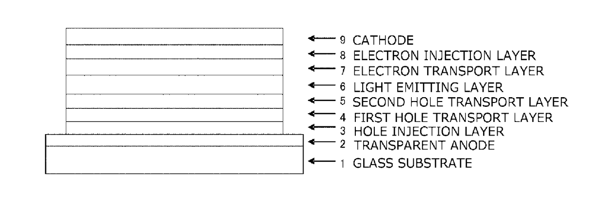
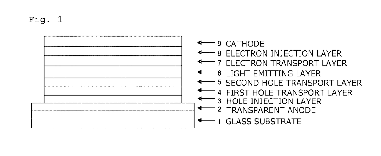
Organic electroluminescent device
a technology of electroluminescent devices and organic materials, which is applied in the direction of luminescent compositions, organic chemistry, triarylamine dyes, etc., can solve the problems of deterioration of devices, inability to achieve improvement in luminous efficiency, and material degradation, so as to improve electron transport efficiency to light emitting layers from electron transport layers, excellent hole and electron injection/transport performance, and stability as a thin film
- Summary
- Abstract
- Description
- Claims
- Application Information
AI Technical Summary
Benefits of technology
Problems solved by technology
Method used
Image

Examples
example 1
Synthesis of 4,4″-bis{(biphenyl-4-yl)-phenylamino}-3-phenyl-1,1′:3′,1″-terphenyl (Compound 1-12)
[0136]4-{(biphenyl-4-yl)-phenylamino}-4″-{(biphenyl-4-yl)-amino}-3-phenyl-1,1′:3′,1″-terphenyl (17.0 g), bromobenzene (4.12 g), palladium acetate (0.13 g), a toluene solution (0.33 mL) containing 50% (w / v) tri-tert-butylphosphine, sodium tert-butoxide (2.73 g), and toluene (190 mL) were added into a nitrogen-substituted reaction vessel. The mixture was heated and stirred at 80° C. for 3 hours. After cooling, the insoluble matter was removed by filtration, and the filtrate was concentrated. The crude product was purified by column chromatography (support: silica gel, eluent:toluene / n-hexane), a solid precipitated by adding acetone was collected, whereby a white powder of 4,4″-bis{(biphenyl-4-yl)-phenylamino}-3-phenyl-1,1′:3′,1″-terphenyl (Compound 1-12; 13.29 g; yield: 71%) was obtained.
[0137]The structure of the obtained white powder was identified by NMR.
[0138]1H-NMR (CDCl3) detected 44 ...
example 2
Synthesis of 4,4″-bis{(biphenyl-4-yl)-phenylamino}-3,3″-diphenyl-1,1′:4′,1″-terphenyl (Compound 1-9)
[0140]4,4″-bis{(biphenyl-4-yl)-amino}-3,3″-diphenyl-1,1′:4′,1″-terphenyl (16.3 g), iodobenzene (18.6 g), copper powder (0.29 g), potassium carbonate (9.61 g), 3,5-di-tert-butylsalicylicacid (1.85 g), sodium hydrogensulfite (0.47 g), dodecylbenzene (20 mL) were added into a nitrogen-substituted reaction vessel. The mixture was heated and stirred at 190 to 200° C. for 17 hours. The mixture was cooled, toluene (1500 mL), a silica gel (40 g), and activated clay (20 g) was added thereto, and stirred. After the insoluble matter was removed by filtration, the filtrate was concentrated. The crude product was purified by recrystallization with chlorobenzene, the recrystallization procedure was repeated to obtain a white powder of 4,4″-bis{(biphenyl-4-yl)-phenylamino}-3,3″-diphenyl-1,1′:4′,1″-terphenyl (Compound 1-9; 9.65 g; yield 49%).
[0141]The structure of the obtained white powder was identi...
example 3
Synthesis of 4-bis(biphenyl-4-yl)amino-4′-{(biphenyl-4-yl)-phenylamino}-2,6-diphenyl-biphenyl (Compound 1-23)
[0144]4-bis(biphenyl-4-yl)amino-2,6-diphenyl-bromobenzene (16.0 g), 4-{N-(biphenyl-4-yl)-N-phenylamino} phenylboronicacid (10.2 g), tetrakistriphenylphosphine palladium (0.60 g), potassium carbonate (4.62 g), water (60 mL), toluene (320 mL), and ethanol (60 mL) were added into a nitrogen-substituted reaction vessel. The mixture was heated, and stirred for 18 hours under reflux. After cooling, water (200 mL) was added thereto, and then an organic layer was collected by liquid separation. The organic layer was dried over anhydrous magnesium sulfate and purified by adsorption with a silica gel (40 g). The organic layer was then concentrated and dispersed and washed using methanol to obtain a crude product.
[0145]The crude product was purified by recrystallization with a toluene / ethanol mixed solvent, and then with ethyl acetate. The recrystallization procedure was repeated to obt...
PUM
| Property | Measurement | Unit |
|---|---|---|
| Time | aaaaa | aaaaa |
| Time | aaaaa | aaaaa |
| Time | aaaaa | aaaaa |
Abstract
Description
Claims
Application Information