Low temperature plasma reaction device and hydrogen sulfide decomposition method

a low temperature plasma reaction and hydrogen sulfide technology, applied in the field of plasma chemistry, can solve the problems of corroding materials, harming human health and polluting the environment, and not being effectively utilized in the conventional hydrogen sulfide recovery process, so as to improve the conversion rate of hydrogen sulfide, reduce the energy consumption of decomposition, and reduce the effect of corrosion

Active Publication Date: 2020-12-24
CHINA PETROCHEMICAL CORP +1
View PDF17 Cites 4 Cited by
  • Summary
  • Abstract
  • Description
  • Claims
  • Application Information

AI Technical Summary

Benefits of technology

[0009]The invention aims to overcome the defects of low conversion of hydrogen sulfide and high decomposition energy consumption when the low-temperature plasma reaction apparatus provided by the prior art is used for decomposing the hydrogen sulfide, and provides a novel low-temperature plasma reaction apparatus capable of improving the conversion of the hydrogen sulfide and reducing the decomposition energy consumption and a method for decomposing the hydrogen sulfide by applying the reaction apparatus.

Problems solved by technology

Hydrogen sulfide (H2S) is a highly toxic and malodorous acid gas, which not only can cause corrosion of materials such as metal, but also harm human health and pollute the environment.
From the viewpoint of comprehensively utilizing resources, the hydrogen resource is not effectively utilized in the conventional hydrogen sulfide recovery process.
Among the aforementioned methods, the high-temperature pyrolysis method is relatively mature in terms of industrial technology, but the thermal decomposition of hydrogen sulfide strongly depends on the reaction temperature and is limited by the thermodynamic equilibrium, and even if the reaction temperature is over 1,000° C., the conversion of hydrogen sulfide is merely 20%.
In addition, the high temperature condition imposes high requirements on the reactor materials, which also increases the operating costs.
Moreover, due to the low conversion of hydrogen sulfide in the pyrolysis process, a large amount of hydrogen sulfide gas needs to be separated from the tail gas and circulated in the system, thereby reducing efficiency of the device and increasing the energy consumption, each the factors brings difficulties to the large-scale industrial application of the device.
Although the membrane technology can be used for effectively separating products, thereby breaking the equilibrium limit and improving the conversion of hydrogen sulfide, the thermal decomposition temperature often exceeds the heat-resistant limiting temperature of the membrane, such that a structure of the membrane material is damaged.
The electrochemical method has the disadvantages such as many operation steps, serious equipment corrosion, poor reaction stability and low efficiency.
However, the method has problems such as a small amount of treatment, low catalytic efficiency, and easy deactivation of the catalyst.
However, the method has the disadvantage that the sulphur produced by the decomposition of hydrogen sulfide will deposit below the catalyst bed.
However, in order to ensure that the hydrogen sulfide is decomposed as sufficiently as possible in the methods disclosed in CN103204466A and CN103204467A, it is necessary to control the flow rate of the hydrogen sulfide so that the residence time thereof in the inner cylinder of the reactor is longer and the size of the inner cylinder is controlled such that more electric energy is obtained per unit volume of gas in the inner cylinder; in addition, given that the current prior art cannot provide a more powerful power source, the methods disclosed in CN103204466A and CN103204467A can only enable the maximum conversion of the hydrogen sulfide to reach about 20% even if the residence time of the hydrogen sulfide is controlled to be longer and the size of the inner cylinder is controlled such that more electric energy is obtained per unit volume of gas in the inner cylinder, moreover, the energy consumption of the hydrogen sulfide decomposition reaction is rather high when the maximum conversion of the hydrogen sulfide reaches about 20%, thus the methods are unsuitable for large-scale industrial applications.
Furthermore, the methods disclosed in CN103204466A and CN103204467A have the disadvantage that the types of available liquid-grounding electrodes are very few, and the disclosed salt solutions and the like can only maintain the temperature of the reactor at less than 100° C. At the temperatures below 100° C., the elemental sulphur is generally in the solid state and is prone to block the reactor.

Method used


Image

  • Low temperature plasma reaction device and hydrogen sulfide decomposition method
  • Low temperature plasma reaction device and hydrogen sulfide decomposition method
  • Low temperature plasma reaction device and hydrogen sulfide decomposition method

Examples


example 1

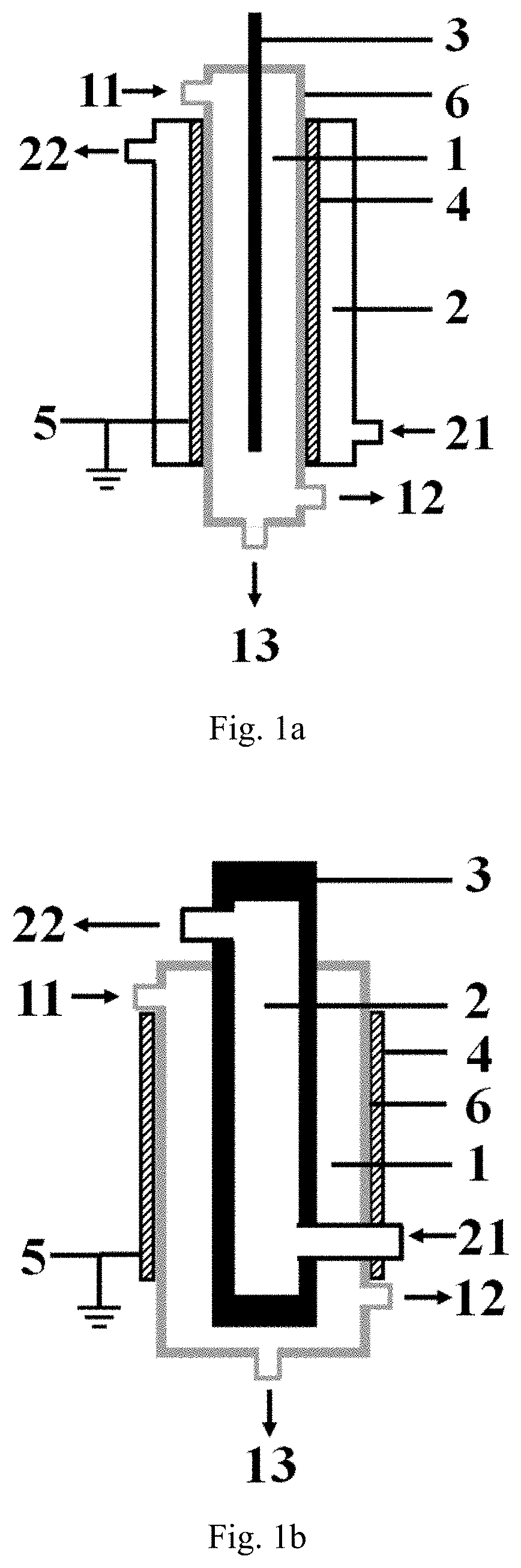
[0119]The low-temperature plasma reaction apparatus illustrated in FIG. 1a is used for performing the hydrogen sulfide decomposition reaction, the specific structure and structural parameters of the low-temperature plasma reaction apparatus are shown as follows, the inner electrode in the example is exactly the high-voltage electrode.

[0120]The reaction apparatus comprises:

a first cavity provided with a first inlet, a gas product outlet and a liquid product outlet, respectively, wherein all the sidewall of the first cavity is formed by the barrier dielectric, the material forming the barrier dielectric is a hard glass;

a second cavity is nested outside the first cavity, and a second inlet and a second outlet are respectively arranged on the second cavity;

an inner electrode arranged at the central axis position of the first cavity, the material forming the inner electrode is stainless steel, and the inner electrode is connected with a high-voltage power supply;

an outer electrode wrappe...

example 2

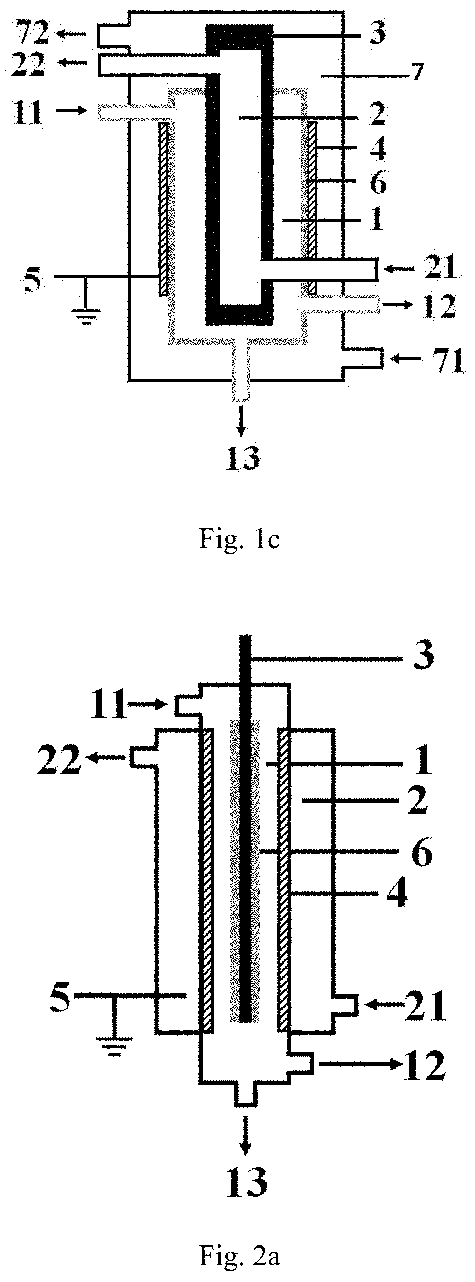
[0133]The example uses a plasma reaction apparatus similar to that of example 1 to carry out the decomposition reaction of hydrogen sulfide, except for that in this example:

all sidewalls of the first cavity are formed by outer electrode, the material forming the outer electrode is stainless steel metal foil, the outer electrode is grounded, and the inner electrode is connected with a high-voltage power supply;

the barrier dielectric is disposed on the inner sidewall of the first cavity in a surrounding manner;

the ratio of L2 to the thickness D1 of the barrier dielectric is 20:1; and L3=1:100.

[0134]In the example, a H2S / Ar mixed gas is introduced into a first cavity of the low-temperature plasma reaction apparatus from a first inlet, wherein the volume fraction of H2S is 30%, the flow rate of the mixed gas is controlled such that the average residence time of the gas in a discharge region is 7.8 s, and the reaction pressure in the first cavity of the reactor in the example is kept at ...

example 3

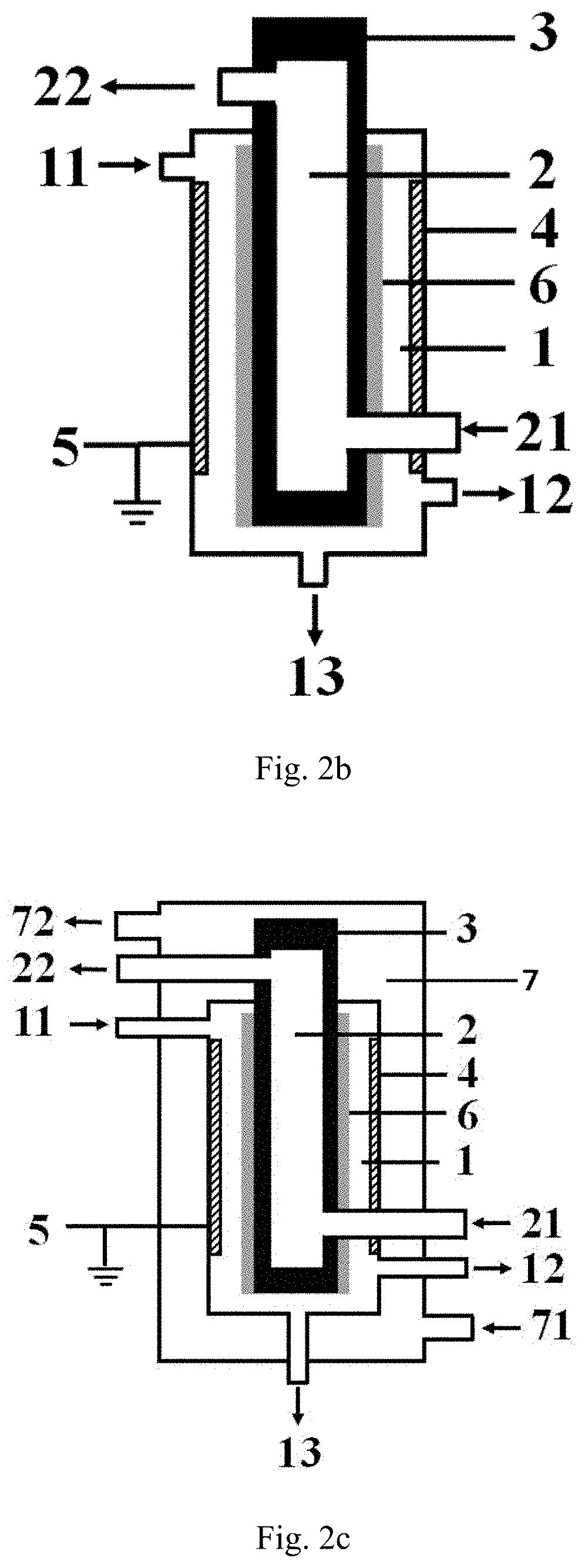
[0137]The example uses a plasma reaction apparatus similar to that of example 1 to carry out the decomposition reaction of hydrogen sulfide, except for that in this example:

all sidewalls of the first cavity are formed by outer electrode, the material forming the outer electrodes is copper foil, the outer electrode is grounded, and the inner electrode is connected with a high-voltage power supply;

the barrier dielectric is disposed on the inner sidewall of the first cavity in a surrounding manner;

the ratio of L2 to the thickness D1 of the barrier dielectric is 0.5:1; and L3=1:200.

[0138]In the example, a H2S / Ar mixed gas is introduced into a first cavity of the low-temperature plasma reaction apparatus from a first inlet, wherein the volume fraction of H2S is 25%, the flow rate of the mixed gas is controlled such that the average residence time of the gas in a discharge region is 10.3 s, and the reaction pressure in the first cavity of the reactor in the example is kept at 0.05 MPa. Af...


PUM

PropertyMeasurementUnit
discharge voltageaaaaaaaaaa
discharge frequencyaaaaaaaaaa
pressureaaaaaaaaaa

Abstract

Described are a low temperature plasma reaction device and a hydrogen sulfide decomposition method. The reaction device includes: a first cavity; a second cavity, the second cavity being embedded inside or outside the first cavity; an inner electrode, the inner electrode being arranged in the first cavity; an outer electrode; and a barrier dielectric arranged between the outer electrode and the inner electrode. The hydrogen sulfide decomposition method includes: implementing dielectric barrier discharge at the outer electrode and the inner electrode of the low temperature plasma reaction device, introducing a raw material gas containing hydrogen sulfide into the first cavity to implement a hydrogen sulfide decomposition method, and continuously introducing a thermally conductive medium into the second cavity in order to control the temperature of the first cavity of the low temperature plasma reaction device.

Description

FIELD OF THE INVENTION[0001]The invention relates to the technical field of plasma chemistry, in particular to a low-temperature plasma reaction apparatus and a method for decomposing hydrogen sulfide.BACKGROUND OF THE INVENTION[0002]Hydrogen sulfide (H2S) is a highly toxic and malodorous acid gas, which not only can cause corrosion of materials such as metal, but also harm human health and pollute the environment. At present, the large and medium oil refineries in China have adopted the traditional Claus method to treat tail gas containing H2S and recover sulphur. The process merely recovers sulphur from the hydrogen sulfide, but converts valuable hydrogen into water. From the viewpoint of comprehensively utilizing resources, the hydrogen resource is not effectively utilized in the conventional hydrogen sulfide recovery process.[0003]Therefore, the decomposition of hydrogen sulfide into sulphur and hydrogen gradually becomes a key technical field attracting attention from scientifi...

Claims


Application Information

Patent Timeline
Patent Type & Authority Applications(United States)
IPC IPC(8): B01J19/08H05H1/24C01B17/04C01B3/04B01J19/24
CPCH05H1/2406B01J19/2445H05H2001/2412C01B3/04B01J2219/0875B01J2219/0896B01J2219/00038B01J19/088B01J2219/0869C01B17/0495H05H2001/245B01J2219/0813H05H2001/2456B01D53/74B01D53/52B01D53/32C01B17/04Y02E60/36C01B2203/0861H05H1/246H05H1/245H05H1/2431H05H2245/15
Inventor ZHANG, JINGMU, SHANJUNXU, WEISHI, NINGZHANG, SHUCAIDONG, GUOSHENGZHANG, TIEWANG, LINREN, JUNPENGSUN, FENG
Owner CHINA PETROCHEMICAL CORP
Why Eureka
Try Eureka