
Plasma process and reactor for producing synthesis gas

a technology of synthesis gas and plasma, which is applied in the field of process and reactor for producing synthesis gas, can solve the problems of deterioration of cathodes, increased cost of process, and increased cost of process, and achieves the effects of easy ionization, high heat power, and simple process

Pending Publication Date: 2022-01-27
PETROLEO BRASILEIRO SA (PETROBRAS) +1
View PDF0 Cites 0 Cited by
  • Summary
  • Abstract
  • Description
  • Claims
  • Application Information

AI Technical Summary

Benefits of technology

The present invention provides a process for generating carbon monoxide and hydrogen, which can enrich natural gas with hydrogen gas by at least 10%. The enriched natural gas can help improve the operation of internal combustion engines with poor mixtures, reducing emissions and improving combustion efficiency. The proposed reactor configuration eliminates the need for cathode shielding gas, resulting in synthesis gas with a higher CO and H2 content, and the highest heat power among all synthesis gas generation technologies. The use of CO2 as a plasma gas solves problems in maintaining plasma discharge and technical-operational difficulties in the power source, and also eliminates the need to generate plasma gas and use it in the process. CO2 is an easily obtainable, non-contaminating or diluent of the synthesis gas generated and is simpler to ionize than hydrogen gas.

Problems solved by technology

However, such processes have parameters that can render the process expensive or impair the process, such as the need to purchase and / or manufacture, regeneration, replacement and disposal of catalysts suitable for each reform process, as well as the use of water (in the case of steam reform), or oxygen (in the case of autothermal or partial oxidation reform).
On the other hand, despite producing synthesis gas of medium heat value, the use of pure oxygen would make the process even more expensive, due to the need for an air separating unit to supply oxygen to the process.
However, the presence of carbon in the reaction medium produces zirconium carbide, which deteriorates the cathode.
According to the authors, the enthalpy and thermal conductivity of the CO2 plasma with CH4 is considerably higher than in plasma with argon, usually used as a protective gas for the cathode and limiting the thermal efficiency of the process.
However, the configuration applied in this document does not allow much flexibility in the amount of methane applied, due to the instability generated in the plasma.
Thus, there are no reports in the state of the art that anticipate a reactor powered by carbon dioxide plasma and a reform process that uses this reactor for the production of synthesis gas with high heat power and nanostructured carbon.

Method used

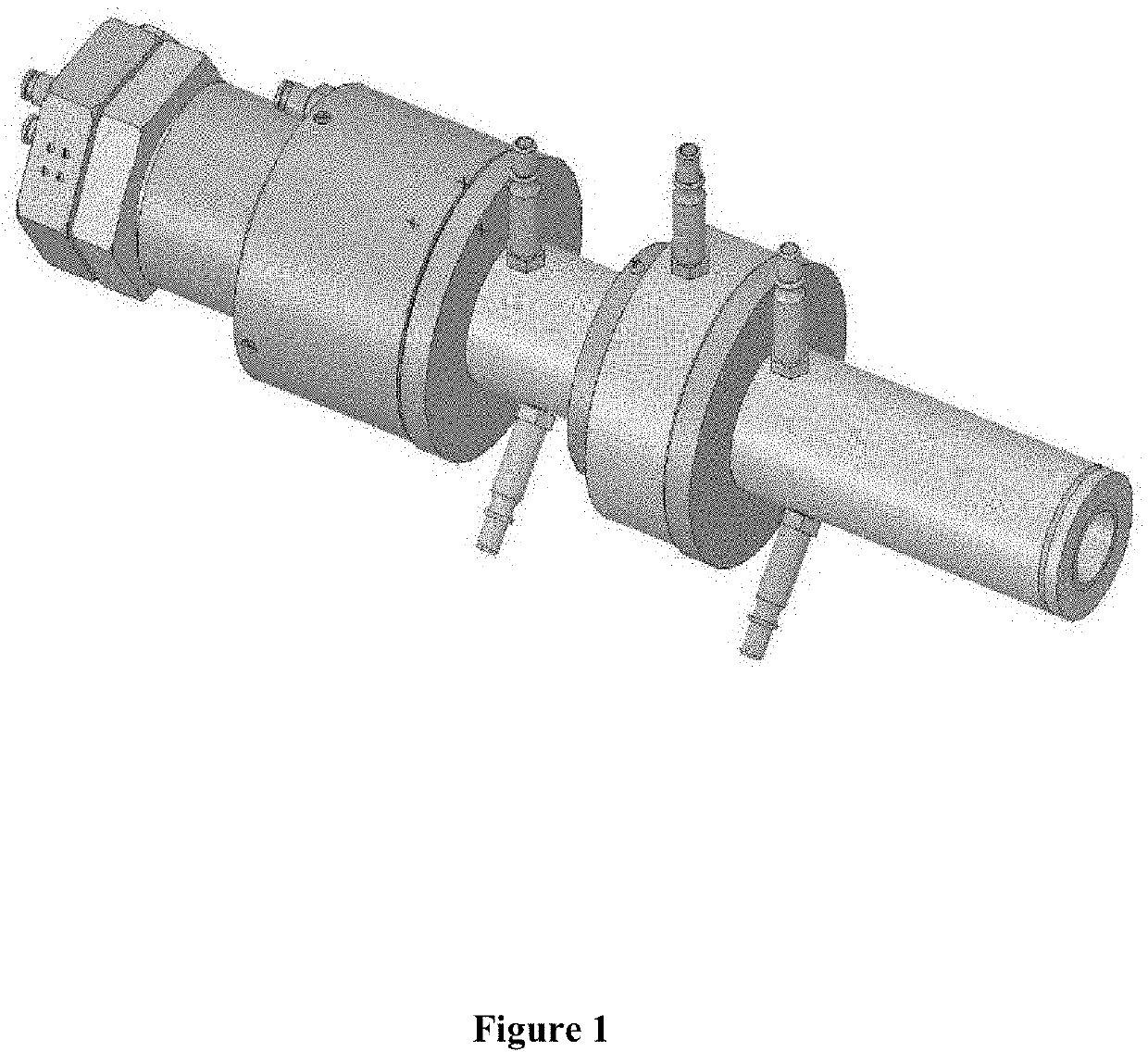
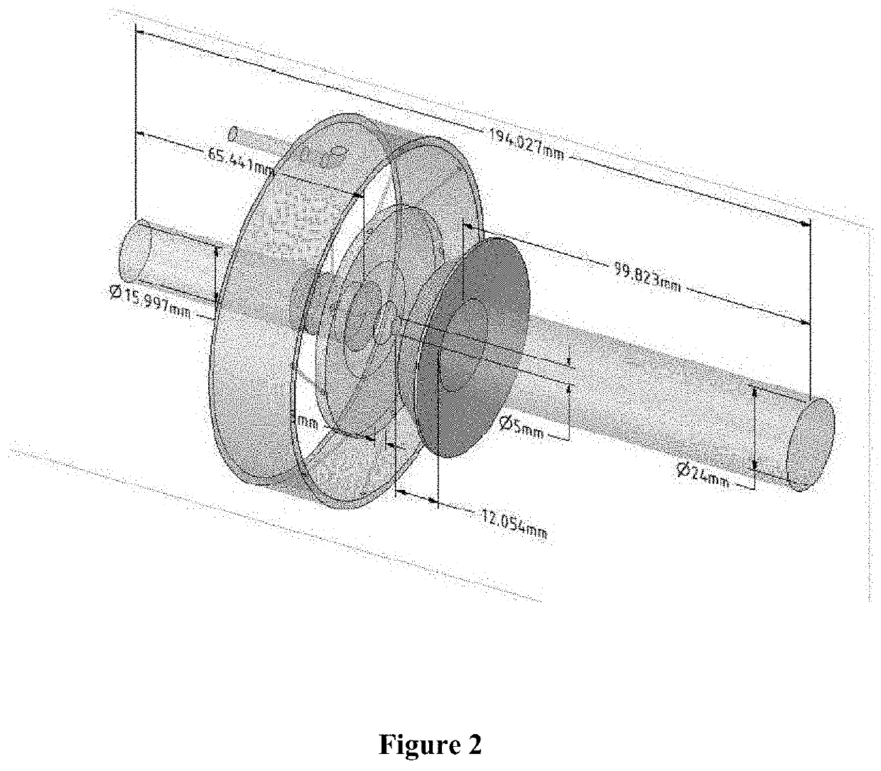

Image

  • Plasma process and reactor for producing synthesis gas
  • Plasma process and reactor for producing synthesis gas
  • Plasma process and reactor for producing synthesis gas

Examples


examples

[0063]For a better understanding of the processes that took place inside the plasma torches, the Computational Fluid Dynamics (CFD—Computational Fluid Dynamics) simulation resource was used. The rendered showed a good energy efficiency in the production of hydrogen, however, with low conversion of CO2. The electric arc thermal plasma torch achieved superior results in converting natural gas into CO2 plasma, in terms of efficiency and scale.

HZR11 Test

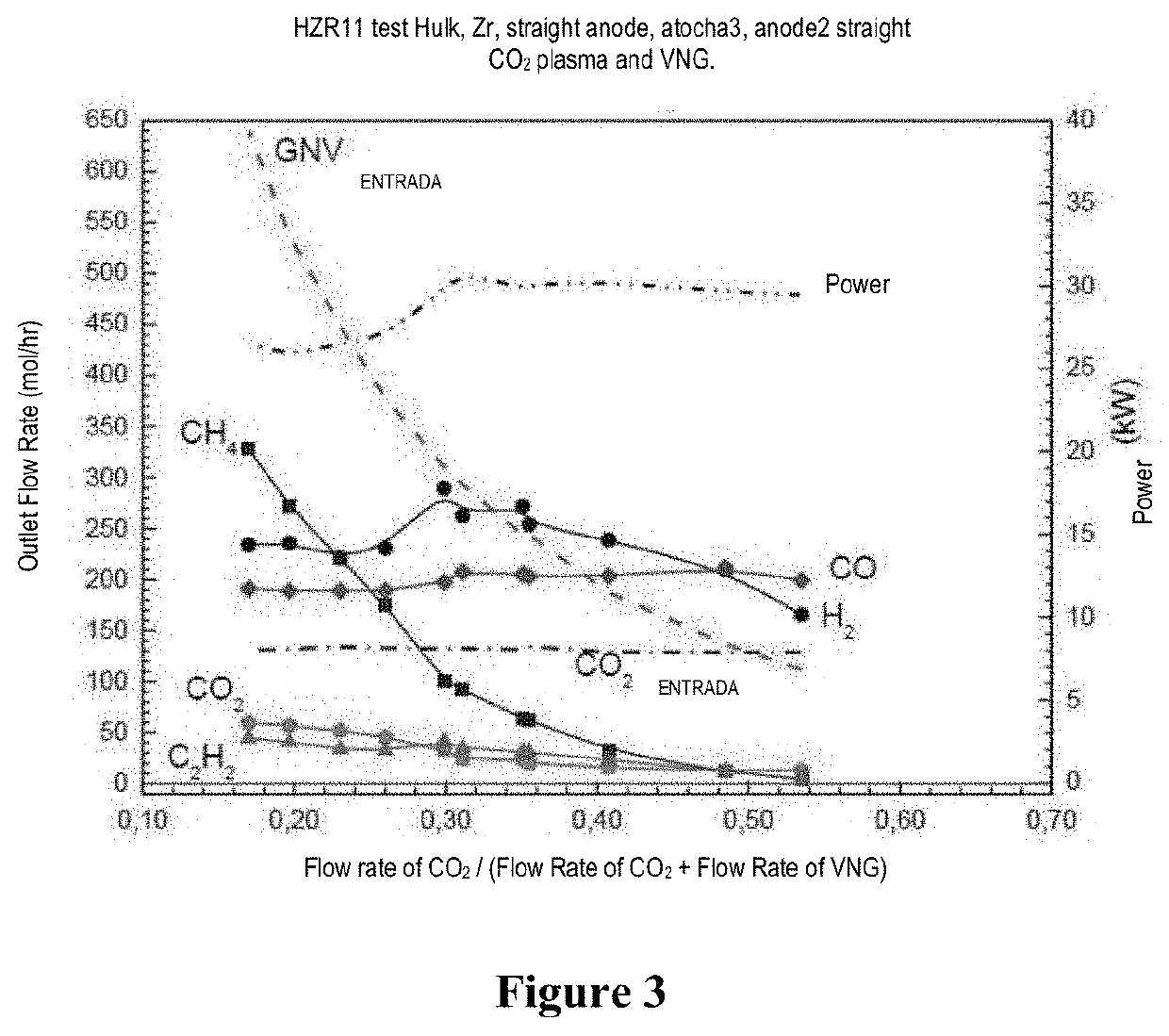
[0064]In order to observe the effects of gas confinement, the second anode had its internal diameter reduced. In this test, the fixed flow rate of 131 mol / hr for CO2 was kept, while the flow rate of VNG was varied from 112 to 639 mol / hr. The current of the electric arc was kept constant at 103 A, but the power decreased with the increase in the flow rate of VNG, due to the small diameter of the second anode that caused an increase in pressure at the output of the first anode. The decrease in the diameter of the second anode, in addition ...


PUM


Abstract

The present invention describes a plasma reactor for processing natural gas and / or light hydrocarbons, including biomethane and biogas, with a plasma torch that does not require the use of cathode shielding gas (shielding gas), as well as a process for reforming using a plasma reactor for the production of synthesis gas and carbonaceous materials from natural gas and / or light hydrocarbons.

Description

FIELD OF PRESENT INVENTION[0001]The present invention refers to a process and reactor for producing synthesis gas. More specifically, the present invention suggests a reactor that makes use of electrical discharges and carbon dioxide and a reform process that uses this reactor for the production of synthesis gas with high heat power and nanostructured carbon.BACKGROUND OF THE PRESENT INVENTION[0002]Hydrogen and hydrogen-rich gases, called synthesis gas, are produced on a large scale for use in the refining industry, in the production of ammonia, methanol, liquid hydrocarbons from the “Fischer-Tropsch” process, in several petrochemical processes and hydrogenation processes of solvents, paraffins and products used in the food industry. To obtain it, some processes of hydrocarbon reform (such as natural gas and / or other light hydrocarbons) can be used, such as, for example, steam reform, partial oxidation, autothermal reform or dry reform. Currently, the process of steam reforming of n...

Claims


Application Information

Patent Timeline
IPC IPC(8): B01J19/08H05H1/34C01B3/34
CPCB01J19/088H05H1/34C01B3/342B01J2219/0898C01B2203/0861B01J2219/0841C01B2203/1241H05B7/18C01B3/34B01J2219/0809B01J2219/0875H05H1/00H05H1/48H05H2245/10C01B2203/0222B01J2219/0883B01J2219/0869B01J12/002
Inventor REIS DA COSTA LABANCA, AURELIOGONÇALVES CUNHA, ALFREDO
Owner PETROLEO BRASILEIRO SA (PETROBRAS)
Learn More