Spark ignition system having a capacitive discharge system and a magnetic core-coil assembly

a technology of capacitive discharge and ignition system, which is applied in the direction of electric ignition installation, mechanical equipment, machines/engines, etc., can solve the problems of increasing hazardous exhaust emissions, loss of engine power and efficiency, and narrowing the availability of suitable core materials

Inactive Publication Date: 2000-09-26
ALLIEDSIGNAL INC +1
View PDF4 Cites 10 Cited by
  • Summary
  • Abstract
  • Description
  • Claims
  • Application Information

AI Technical Summary

Benefits of technology

Generally stated, the magnetic core-coil assembly of the present invention comprises a magnetic core composed of a ferromagnetic amorphous metal alloy which has low magnetic losses coupled with fewer primary and secondary coil windings due to the magnetic permeability of the core material. The core-coil assembly has a single primary coil connected to the CD system for voltage excitation therefrom and a secondary coil for a high voltage output. The secondary coil comprises a plurality of core-coil sub-assemblies, each having an amorphous metal core and a coil. The coils of the core-coil sub-assemblies are alternately wound in the clockwise and counter-clockwise directions such that adjacent coils are not wound in the same direction. The alternating coil windings of the core-coil sub-assemblies provide a high voltage output from the secondary coil that is the sum of the voltages generated by each of the core-coil sub-assemblies. When the main storage capacitor of the CD system discharges, the core-coil assembly acts as a pulse transformer; stepping-up the voltage output from the CD system (i.e. between approximately 300 and 600 volts DC) based on the turns ratio of secondary to primary coil of the core-coil assembly. The output voltage generated by the core-coil assembly of the present invention can exceed 30 kilovolts (kV) The low number of primary and secondary coil windings (i.e. turns) provide a core-coil assembly having a lower resistance and inductances than prior art inductive core-coil assemblies. As a result, the present invention provides improved multi-strike capabilities, when compared to prior art core-coil assemblies, due in part to the rapid discharge time of the main storage capacitor of the CD system, which is related to the overall construction of the core-coil assembly.
More specifically, the core of the core-coil assembly is composed of an amorphous ferromagnetic material which exhibits low core loss and a permeability (ranging from about 100 to 500). Such magnetic properties are especially suited for rapid firing of the spark plug during a combustion cycle. Misfires of the engine due to soot fouling are minimized. Moreover, energy transfer from coil to plug is carried out in a highly efficient manner. The low secondary resistance of the generally toroidal core design (typically, less than 50 ohms) provides secondary peak currents several times higher than conventional, prior art CD systems and permits the bulk of the energy to be dissipated in the spark and not in the secondary winding of the core-coil assembly. The individual secondary voltages generated across the plural core-coil sub-assemblies rapidly increase and add sub-assembly to sub-assembly based on the total magnetic flux change of the system. This allows the versatility to combine several core-coil sub-assemblies wound via existing toroidal coil winding techniques to produce a single assembly with superior performance. As a result, the core-coil assembly of the invention is less expensive to construct, and more efficient and reliable in operation than core-coil assemblies having a single secondary coil.

Problems solved by technology

A spark event which is too late leads to loss of engine power and efficiency.
Engine misfiring increases hazardous exhaust emissions.
Numerous cold starts without adequate heat in the spark plug insulator in the combustion chamber can lead to misfires, due to deposition of soot on the insulator.
The combination of these required properties narrows the availability of suitable core materials.
Conventional silicon steel routinely used in utility transformer cores is inexpensive, but its magnetic losses are too high.
Thinner gauge silicon steel with lower magnetic losses is too costly.
The dimensional requirements of the spark plug well limit the type of configurations that can be used.
The discharge time of such a core-coil assembly would be very short due to core saturation.
One of the drawbacks to this type of design was the aspect ratio of the toroidal core 10 and the number of secondary turns required for general operation.
Typical toroid winding machines are not capable of winding coils near this aspect ratio due to their inherent design.
Typically the time to wind these coils was very long.
The elongated toroid design, though functional would be difficult to mass produce at a sufficiently low cost to be commercially attractive.
This voltage distribution is in effect over the entire height of the coil structure and thus results in voltage stress at and around the last turns of the secondary coil.

Method used


Image

  • Spark ignition system having a capacitive discharge system and a magnetic core-coil assembly
  • Spark ignition system having a capacitive discharge system and a magnetic core-coil assembly
  • Spark ignition system having a capacitive discharge system and a magnetic core-coil assembly

Examples


Embodiment Construction

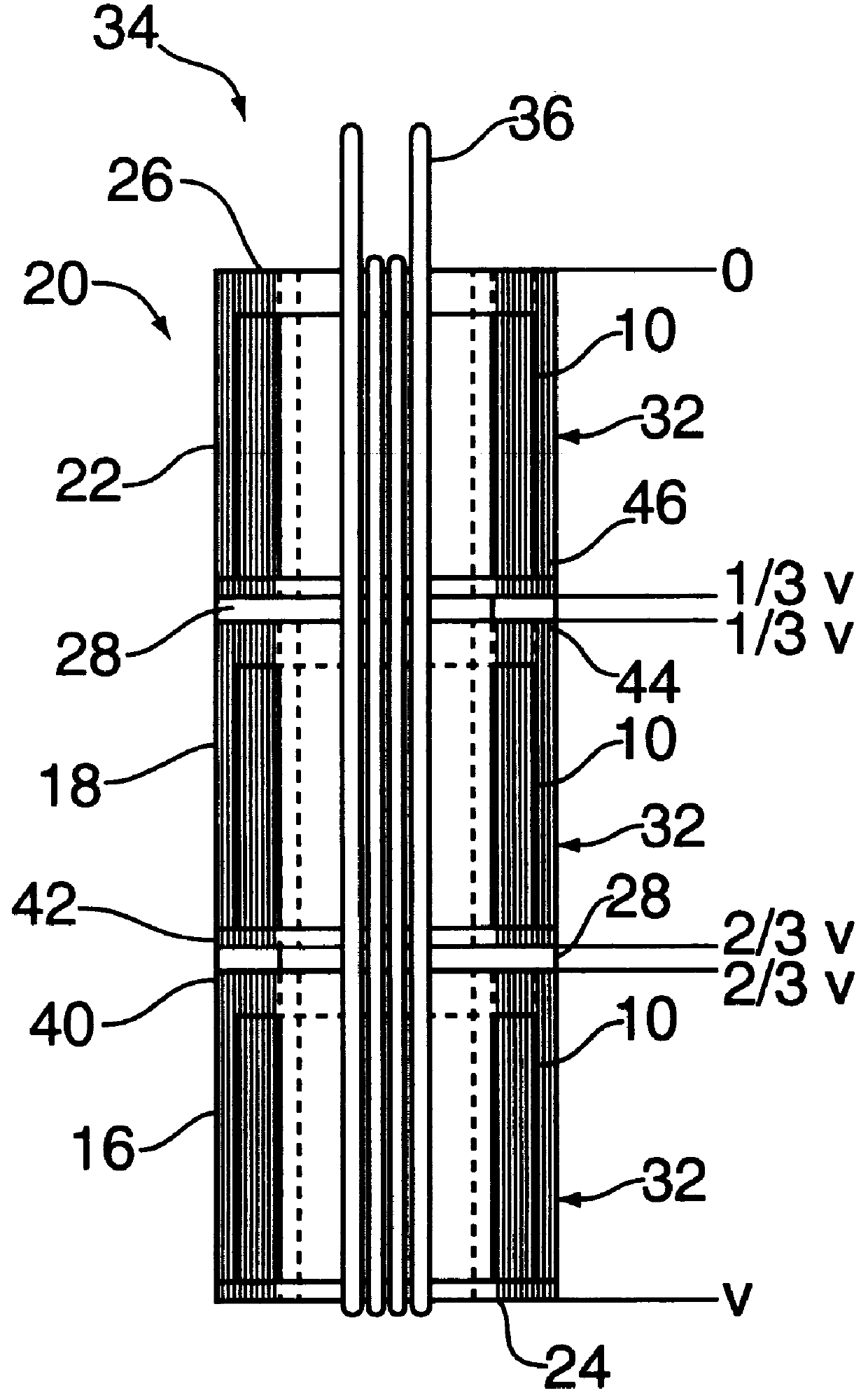
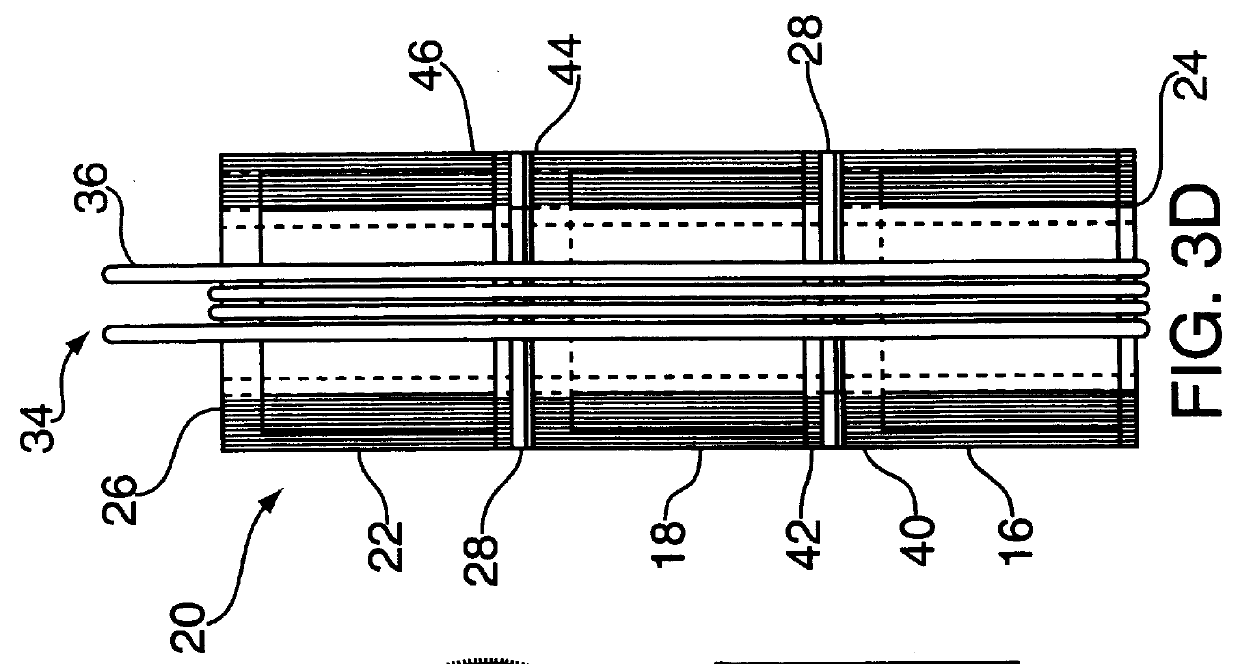
An amorphous iron-based ribbon having a width of about 15.6 mm and a thickness of about 20 .mu.m was wound on a machined stainless steel mandreland spot welded on the inside or inner diameter and outside or outer diameter to maintain tolerance. The inside diameter of 12 mm was set by the mandrel and the outside diameter was selected to be 17 mm. The finished cylindrical core weighed about 10 grams. The cores were annealed in a nitrogen atmosphere in the 430.degree. to 450.degree. C. range with soak times from approximately 2 to 16 hours. The annealed cores were placed into insulator cups and wound on a toroid winding machine with 190 turns of thin gauge insulated copper wire as the secondary coil. Both counterclockwise (ccw) and clockwise (cw) units were wound. A ccw winding direction was used for the bottom and top core-coil assemblies while a cw winding direction was used for the middle assembly. Insulator spacers were added between adjacent core-coil assemblies. Three (3) turns o...


PUM

PropertyMeasurementUnit
voltagesaaaaaaaaaa
discharge timeaaaaaaaaaa

Abstract

A spark ignition system for an internal combustion engine has a capacitive discharge (CD) system connected to a coil-per-plug (CCP) magnetic core-coil assembly. The spark ignition system is connected to a spark plug and is adapted to initiate an ignition wherein a spark is produced across the gap of the spark plug. The spark ignition system includes a magnetic core-coil assembly having an amorphous metal magnetic core, a primary coil and a secondary coil for a high voltage output to be fed to a spark plug. The CD system is charged and rapidly discharged through the primary coil of the magnetic core-coil assembly using a silicon controlled rectifier (SCR) as the switch. Operation of the SCR is controlled by circuitry that controls the firing of the spark ignition system. The magnetic core-coil assembly acts as a pulse transformer, so that voltage across its secondary coil is related to the turns ratio of secondary to primary.

Description

1. Field of the InventionThis invention relates to spark ignition systems for internal combustion engines; and more particularly to a spark ignition system including a capacitive discharge system and a core-coil assembly which improves performance of the engine system and reduces the size of the magnetic components in the spark ignition transformer in a commercially producible manner.2. Description of the Prior ArtIn a spark-ignition internal combustion engine, a flyback transformer is commonly used to generate the high voltage needed to create an arc across the gap of the spark plug and cause an ignition event, i.e., igniting the fuel and air mixture within the engine cylinder. The timing of this ignition spark event is critical for best fuel economy and low exhaust emission of environmentally hazardous gases. A spark event which is too late leads to loss of engine power and efficiency. Correct spark timing is dependent on engine speed and load. Each cylinder of an engine often req...

Claims


Application Information

Patent Timeline
Patent Type & Authority Patents(United States)
IPC IPC(8): F02P3/02H01F38/12H01F38/00F02P3/01F02P15/00
CPCF02P3/02H01F38/12F02P3/01
Inventor RAPOPORT, WILLIAM ROSSPAPANESTOR, PAUL ALEXANDER
Owner ALLIEDSIGNAL INC
Why Eureka
Try Eureka