Method of making a supported plurality of electrochemical extruded membranes

a technology of electrochemical extrusion and supported plurality, which is applied in the field of improving the method of manufacturing a supported plurality of electrochemical extrusion membranes, can solve the problems of increased vibration amplitude, the geometrical structure of such afc cannot be effectively used in a variable vibration environment, and the material waste of the accompanying mass cannot be effectively used. to achieve the effect of facilitating the support of the membran

Inactive Publication Date: 2001-09-25
FORD GLOBAL TECH LLC
View PDF6 Cites 19 Cited by
  • Summary
  • Abstract
  • Description
  • Claims
  • Application Information

AI Technical Summary

Benefits of technology

It is an object of the present invention to provide an improved method of manufacturing a supported plurality of electrochemical extruded membranes. The method includes providing a first mixture at a first temperature and a second mixture at a second temperature, extruding the first mixture to form a plurality of spaced-apart supportable membranes, and cooling the extruded membrane from the first temperature to a third temperature. The method further includes forming sufficient bubble surfaces of the second mixture between the membranes to facilitate the support of the membranes, cooling the extruded membranes and the formed bubble surfaces to a semi-solid from the second temperature to the third temperature less than the first and second temperatures, and heating the cooled extruded membranes and the cooled formed bubble surfaces from the semi-solid at the third temperature to a predetermined elevated temperature sufficient to make the extruded membranes and the formed bubble surfaces into a sintered ceramic. The method further comprises sufficiently cooling the extruded membranes and the formed bubble surfaces in the sintered ceramic to cause the bubble surfaces to support the membranes.
In box 218, the method includes forming sufficient bubble surfaces of the second mixture between the membranes to facilitate the support of the membranes. After a sufficient length of the membranes has been extruded and bubbles formed thereon, the membranes are cut from the die. In box 220, the method includes cooling the extruded membranes in the formed bubble surfaces to a semi-solid from the second temperature to the third temperature. After reaching ambient temperature, the tubing can be easily handled and stored without the use of a mandrel.
The sacrificial binder employed in the method of this invention includes a plasticizer comprising oil and a wax in combination. The oils and waxes used for this purpose are naphthenic, paraffinic or a mixture of paraffinic and naphthenic constituents. They are sufficiently volatile to be removed easily and rapidly in the burnout process but insufficiently volatile to be substantially removed during mixing and / or molding. The loss due to volatilization during mixing and / or molding is advantageously below 20 and preferably below 10 weight percent. The selection is such that their evolution during burnout takes place over a broad temperature range, thus avoiding stress points and defects in parts.
Functionally, the oils and waxes must be compatible with the rubbery phase of the principal binder resin when it becomes rubbery on plasticization at a temperature somewhat below the softening point of the "A" segments of the principal resin. This gives the binder a capability of accepting higher filler loadings while remaining strong and flexible.
For example, if the "A" block of the block copolymer is a polystyrene, then the first stiffening thermoplastic polymer preferably is a polystyrene or other thermoplastic aromatic polymer. In addition to stiffening, such a thermoplastic polymer should also aid in mixing the sacrificial binder composition ingredients. A thermoplastic polystyrene polymer such as Styron 495.TM., marketed by Dow Chemical Company, does this because it ha a lower viscosity than the thermoplastic block copolymer at processing conditions; on the other hand it is sufficiently crystalline at room temperature to advantageously stiffen the formed green body. Furthermore, according to this example, if the first stiffening polymer is polystyrene as mentioned, the second stiffening polymer is aromatic but has a different aromatic moiety, e.g., indene. A preferred second polymer is polyindene. Low molecular weight polyindenes have the further advantage of low viscosity at processing conditions. The low viscosity aids flow of the sacrificial binder compositions.
Other ingredients may be employed in the binders of this invention. For example, antioxidants are useful to retard oxidative degradation of the block polymer during mixing, thus minimizing loss of strength in the green body. The antioxidant also allows more rapid removal of binder during burnout by minimizing surface oxidation which may tend to seal off the surface. Suitable antioxidants include, but not by way of limitation, 2,6-ditert-butyl-phenol, a polymerized 1,2-dihydro-2,2,4-trimethyl quinoline, 2-mercaptobenzimidazole, tetra-bis-methylene-3-(3,5-ditert-butyl-4-hydroxy phenyl)propionate methane, etc.

Problems solved by technology

However, the honeycomb structure wastes material and the accompanying mass that are not actively employed in the electrochemical conversion.
Although elongated tubular solid oxide fuel cells have been effectively used in stationary systems, the geometrical structure of such SOFC cannot be effectively used in a variable vibration environment such as a vehicle in which vibration across a wide range of frequencies is anticipated to be present during routine operation.
In such an environment, the cells will at some point begin to vibrate in resonance at which time the amplitude of the vibration will increase greatly with adverse consequences, such as breaking at a point of connection or at impact with other tubes.
Although honeycomb structural bodies have been used to withstand the vibration in the exhaust systems of vehicles, the power density of the solid oxide fuel cells based on honeycombs is decreased, increasing the total weight and cost of the material in the chemical-to-electrical conversion system.
Many honeycomb structures have geometric structures resulting in much unused material and thus less power density.

Method used


Image

  • Method of making a supported plurality of electrochemical extruded membranes
  • Method of making a supported plurality of electrochemical extruded membranes
  • Method of making a supported plurality of electrochemical extruded membranes

Examples


example 1

is of an electrolyte supported solid oxide fuel cell. In this example, Mixture 1 is a fully-stabilized micron-sized YSZ powder compounded with the special thermoplastic elastomer binder. Mixture 2 is made of the same yttria-stabilized zirconia (YSZ) powder in same binder but with sufficient toluene added to lower viscosity.

In particular Mixture 1 consists of 9.6 g Calprene.TM. (Dynasol Corp.), 1.4 g Styron.TM. 495R (Dow Plastics), 2 g paraffin wax #32721-2 (Sigma-Aldrich), 2 g paraffin wax #31765-9 (Sigma Aldrich), 1.4 g Picco.TM. 5140 hydrocarbon resin (Hercules), 2 g Flexon.TM. 845 (Exxon), 3.4 g Shellflex.TM. 371 (Equilon), 1 g AgeRite.TM. Resin D (R. T. Vanderbilt), and 44 g of yttria-stabilized zirconia (FYT 13.0-001 of Muscle Shoals).

In particular, Mixture 2 consists of all of the above constituents of Mixture 1, plus 25 g toluene, dissolved in at 50 degrees Celsius.

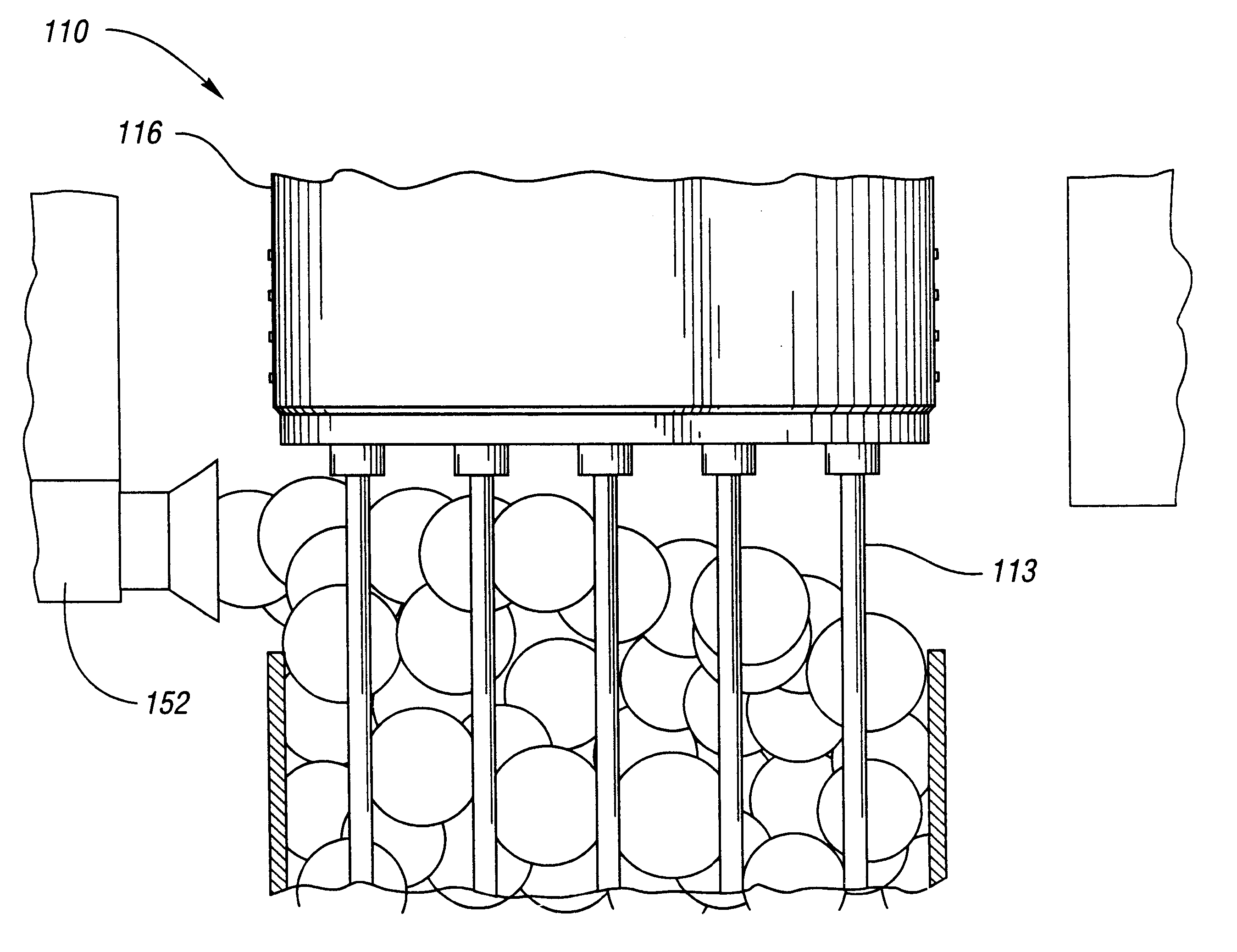
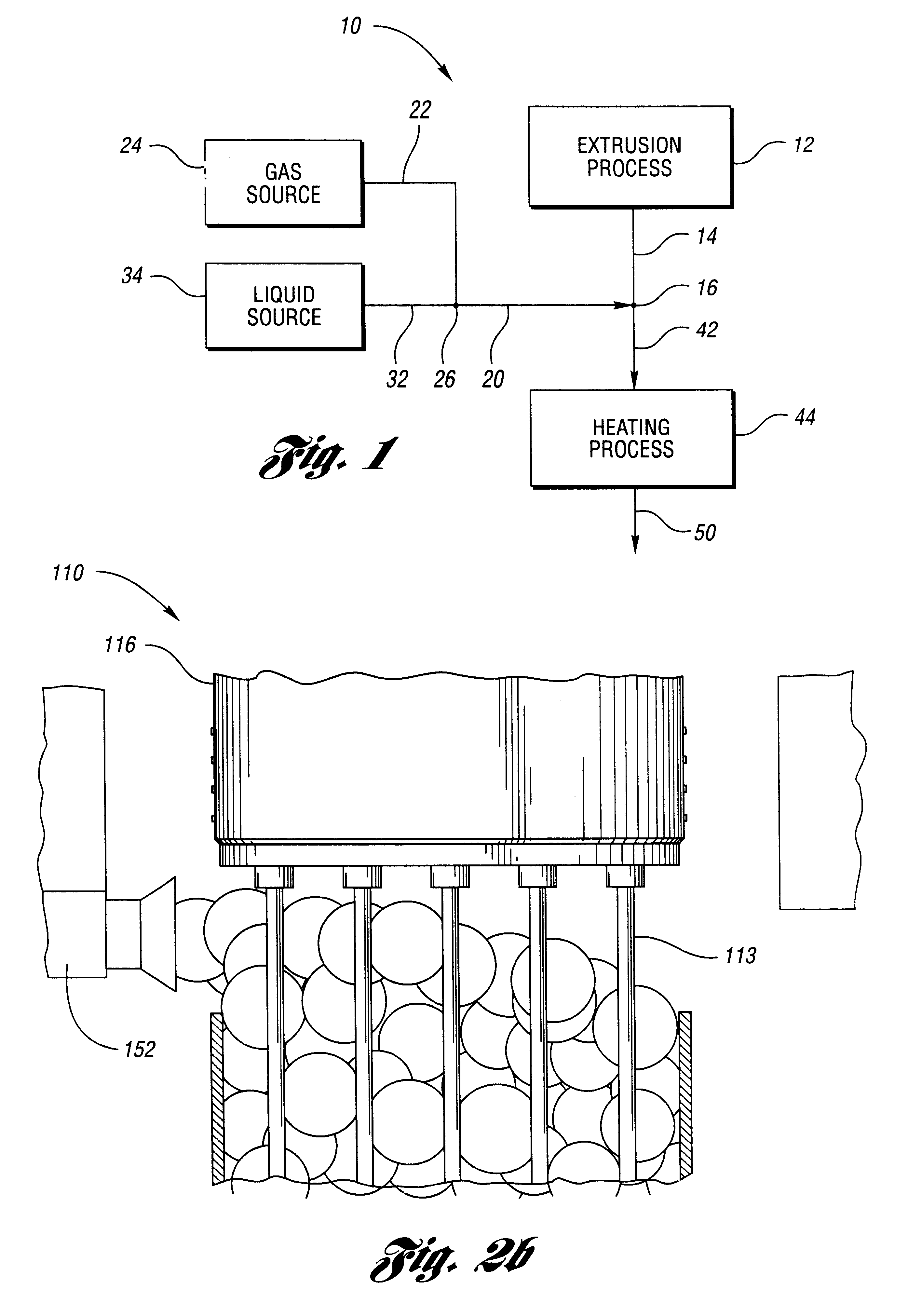
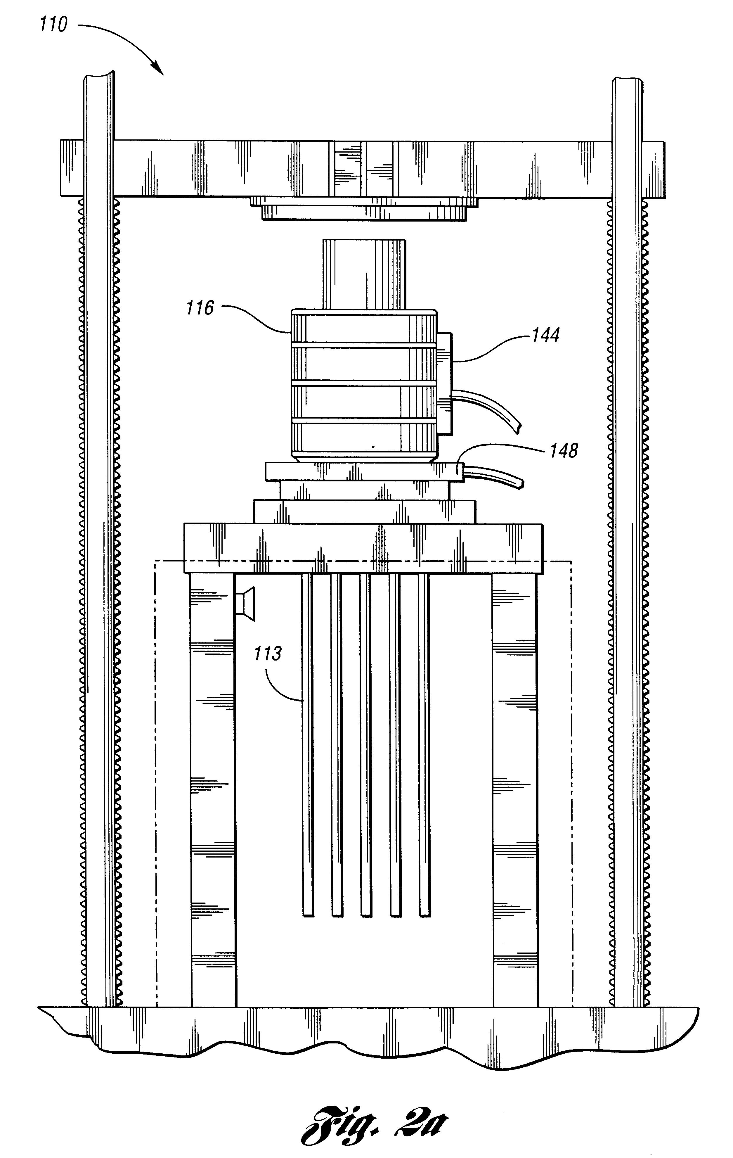
Mixture 1 is extruded at 130 deg C. Bubble surfaces are formed from Mixture 2 after the 19 tubes of diameter eac...

example 2

is of an electrolyte supported solid oxide fuel cell with the membranes having a stellate cross-section, instead of the circular cross-section of Example 1, in order to enlarge the surface area of the electrolyte. Each of the 19 tube extrusion dies consists of matching pairs of six-pointed star shapes with rounded corners and sharpest interior angles of 30 deg angular. The extrusion of Mixture 1 thus produces tubes with stellate cross-section and wall thickness of 0.2 mm and circumscribed outside diameter of 2.4 mm. Subsequent processing steps are as given in Example 1 to produce assemblages that can produce voltages. Because of the higher surface area, the power density is expected to be 30% higher than for Example 1.

example 3

is of an electrolyte supported fuel cell with highly active electrode layers immediately adjacent to the electrolyte. The extrusion and bubble surfaces are formed as in Example 1. However, an additional step is added at the stage of coating the anode and the cathode. In particular, after masking the sides of the hexagonal assemblage, a sol-gel precursor of gadolinia-doped ceria is applied to the inside of the 19 tubular membranes to form a 5 micron layer on the inside diameter. The remainder of the anode is formed by dip coating, as in Example 1. After firing, the highly active anode layer has a finer pore size and a higher electrochemical exchange current than is found in the bulk thickness of the dip-coated anode. To produce a similarly highly activated layer, after masking the top and bottom of the assemblage, a ceria-manganite-producing sol-gel coating is applied to the cathode side. The remainder of the cathode is formed by dip coating, as in Example 1. After firing, the highly...


PUM

PropertyMeasurementUnit
temperatureaaaaaaaaaa

Abstract

The present invention is a method for the manufature of a membrane structure for use in electrochemical conversions. The method includes providing a first mixture at a first temperature and a second mixture at a second temperature, extruding the first mixture to form a plurality of spaced-apart supportable membranes, cooling the extruded membrane from the first temperature to a third temperature, forming sufficient bubble surfaces of the second mixture between the membranes to facilitate the support of the membranes, cooling the extruded membranes and the formed bubble surfaces to a semi-solid from the second temperature to the third temperature less than the first and second temperatures, heating the cooled extruded membranes and the cooled formed bubble surfaces from the semi-solid at the third temperature to a predetermined elevated temperature sufficient to make the extruded membranes and the formed bubble surfaces into a sintered ceramic, and sufficiently cooling the extruded membranes and the formed bubble surfaces in the sintered ceramic to cause the bubbles to support the membranes.

Description

The present invention relates to a supported plurality of electrochemical extruded membranes and a method of manufacturing the supported membranes.Chemical-to-electrical conversion technology continues to be researched, as the demand increases for higher fuel efficiency. The technical approaches regarding electrochemical conversions are numerous. Moreover, the device applications are also many. For example, electrochemical cells may be used as a NOx decomposing means, wherein the cell is used as a purifier for exhaust gases from an automobile or an electric power-generating apparatus. Moreover, the electrochemical cells may be used for cogeneration for heating domestic hot water together with electrical power.In particular, solid oxide fuel cells (SOFC) and the derivative technologies are efficient electrochemical cells which can be used for such purposes. Solid oxide fuel cells with membranes formed by extrusion have been used in stationary but not mobile chemical-to-electrical con...

Claims


Application Information

Patent Timeline
Patent Type & Authority Patents(United States)
IPC IPC(8): B32B18/00C04B35/486H01M8/12
CPCB32B18/00C04B35/486H01M8/124H01M4/9033H01M8/1253H01M2300/0068C04B2237/565Y02E60/525C04B2235/602C04B2235/6562C04B2235/6565C04B2235/6567C04B2237/348Y02E60/521Y02E60/50Y02P70/50
Inventor CROSBIE, GARY MARK
Owner FORD GLOBAL TECH LLC
Why Eureka
Try Eureka