Multiple source deposition process

a multi-source deposition and electroluminescent technology, applied in the direction of vacuum evaporation coating, inorganic insulators, coatings, etc., can solve the problems of increasing the power consumption of the display, reducing reliability, and not achieving the phosphor luminance of the electroluminescent display

Inactive Publication Date: 2003-08-26
IFIRE IP CORP
View PDF17 Cites 25 Cited by
  • Summary
  • Abstract
  • Description
  • Claims
  • Application Information

AI Technical Summary

Problems solved by technology

However, even with the enhanced luminosity that is obtained, electroluminescent displays employing a thick film dielectric layer have not achieved the phosphor luminance and colour coordinates needed to be fully competitive with cathode ray tube (CRT) displays.
Some improvement has been realized by increasing the operating voltage of electroluminescent displays, but this increases the power consumption of the displays, decreases the reliability and increases the cost of operating electronics for the displays.
For displays with high resolution, however, the shadow mask technique does not provide adequate accuracy, and photolithographic methods must be employed.
Some phosphor materials, for example strontium sulphide are susceptible to hydrolysis, and water and protic solvents may degrade the properties of the phosphor materials.
However, such a design modification demands increased performance from the phosphor materials used for the red and green phosphor materials, and requires the use of higher display operating voltages.
The higher operating voltages increase the power consumption of the display, decrease the reliability and increase the cost of operating the electronics of the display.
The optical emission from these phosphor materials must be passed through an appropriate chromatic filter to achieve the necessary colour coordinates for red, green and blue sub-pixels, resulting in a loss of luminance and energy efficiency.
These include cerium activated alkaline earth thiogallate compounds, which give good blue colour coordinates, but have relatively poor luminosity and stability.
Since the host materials are ternary compounds, it is relatively difficult to control the stoichiometry of the phosphor films.
Europium-activated barium thioaluminate provides excellent blue colour coordinates and higher luminance, but it too is a ternary compound whose stoichiometry is difficult to control.
Vacuum deposition of phosphor films comprising europium-activated barium thioaluminate from a single source pellet using sputtering or electron beam evaporation has not yielded films with high luminosity.
However, this technique is not readily scalable to facilitate commercial production of large area displays and the process cannot be controlled to compensate for changes in the evaporation rates from the two sources as the deposition proceeds and the source pellets are depleted.

Method used


Image

  • Multiple source deposition process
  • Multiple source deposition process
  • Multiple source deposition process

Examples


example ii

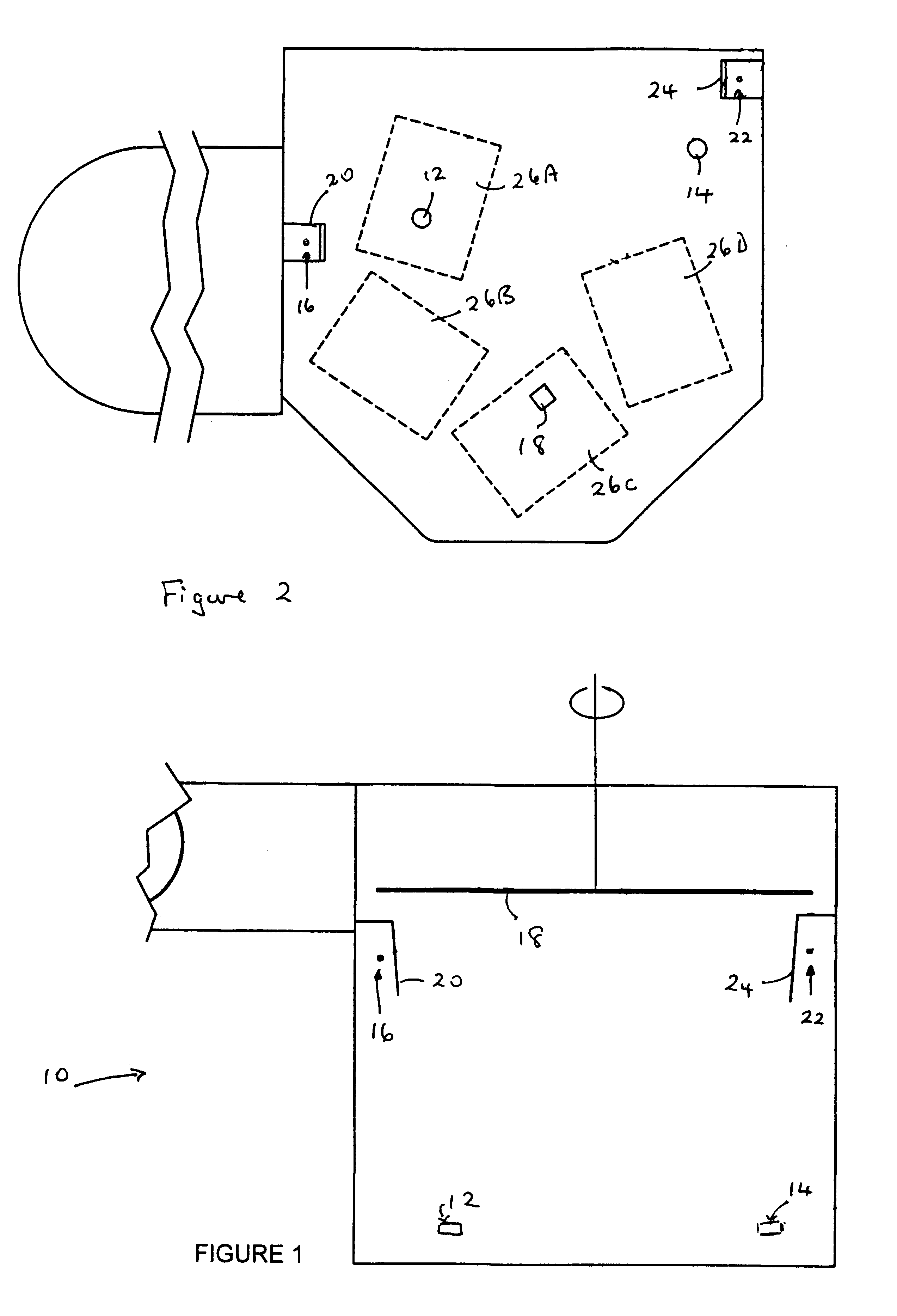
A europium-doped calcium thioaluminate phosphor film of the type described in Example 1 with a=0 was formed on a thick film opaque substrate using the dual source method and apparatus described above.

One of the two source materials used to deposit the phosphor was aluminum sulphide (Al.sub.2 S.sub.3) formed into a pellet. This pellet was not annealed. The other source material was a europium-doped calcium sulphide pellet (CaS:Eu). This pellet was annealed at 800.degree. C. for 20 minutes in nitrogen. The diameter and height of each of the Al.sub.2 S.sub.3 and CaS:Eu pellets were 2.5 and 1.8 centimeters, respectively. The pellets were slowly degassed and preconditioned with a low electron beam current from their respective electron guns.

The substrate was alumina upon which a gold electrode pattern was deposited and overlaid with a high dielectric constant thick film dielectric layer comprising PMN-PT coated with lead zirconate-titanate, and further overlaid with a thin film layer of ...

example iii

A phosphor film was prepared using the material described in Example 1 with a=1. The procedure used was the same as that described in Example I. For this phosphor, one pellet was formed from Al.sub.2 S.sub.3 and the other pellet was formed from the required mixture of barium sulphide and europium sulphide. The thickness of the BaAl.sub.2 S.sub.4 :Eu phosphor film was 2700 Angstroms, measured using scanning electron microscopy.

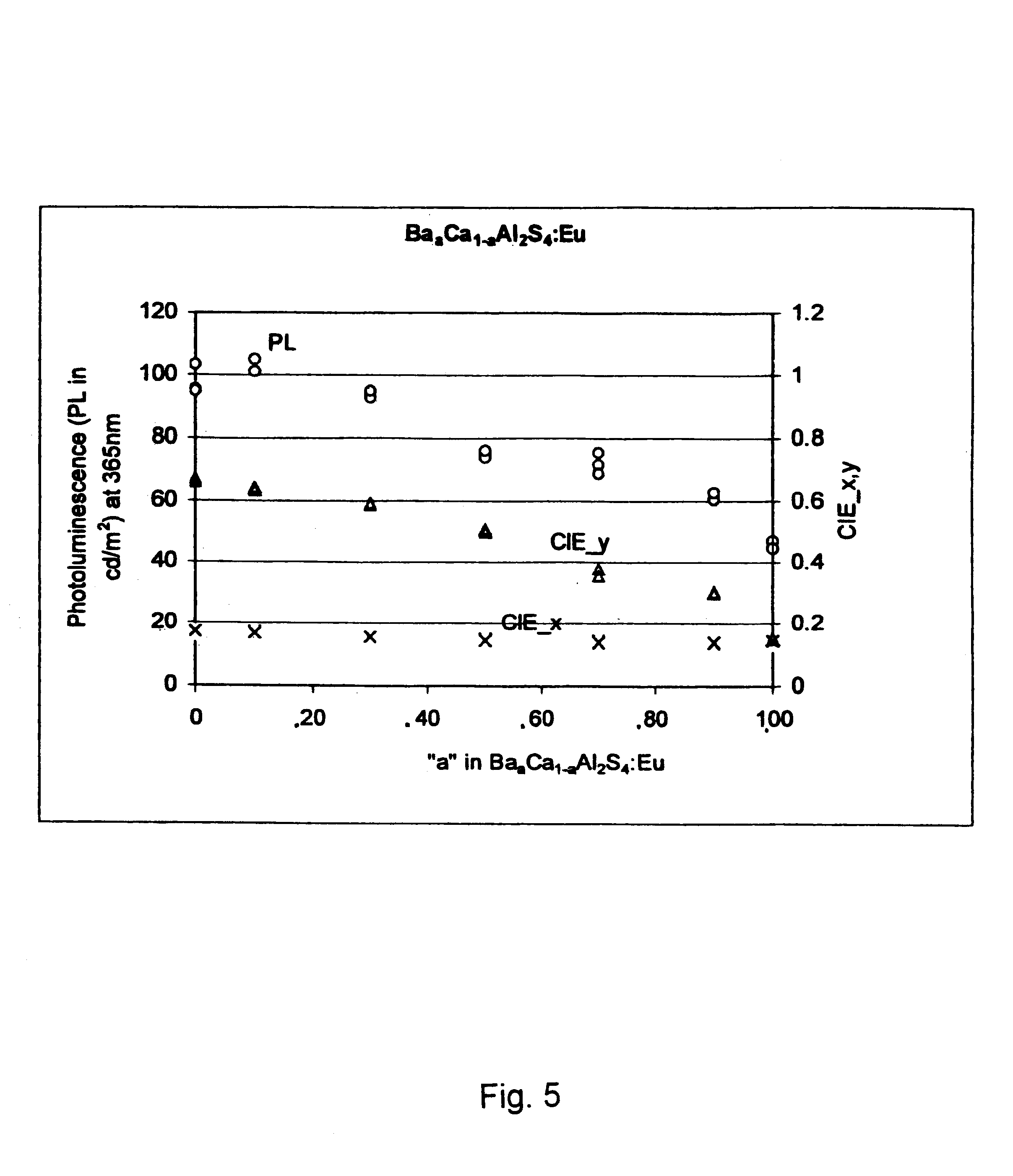
As reported in Example I, for the composition corresponding to a=0, i.e. CaAl.sub.2 S.sub.4 :Eu, and using an excitation frequency of 120 Hz and a pulse width of 30.mu. seconds, the electroluminescent pixel had a brightness of 90 cd / m.sup.2 at 70 volts above the threshold voltage of 180 volts while its CIE colour coordinates were x=0.19 and y=0.62. This is reasonably similar to the photoluminescence values observed for the pellets having the same nominal composition.

For the composition corresponding to a=1, i.e. BaAl.sub.2 S.sub.4 :Eu, the luminance was about 4...


PUM

PropertyMeasurementUnit
heightaaaaaaaaaa
diameteraaaaaaaaaa
heightaaaaaaaaaa

Abstract

A method for the deposition of a thin film of a pre-determined composition e.g. a phosphor, onto a substrate, in which the composition is a ternary, quaternary or higher composition, especially a composition selected from the group consisting of thioaluminates, thiogallates and thioindates of at least one element from Groups IIA and IIB of the Periodic Table. In the embodiment, the method comprises placing a pellet of at least one sulfide on a first source and placing a pellet of at least one sulfide on a second source, with one pellet containing dopant. Vapor deposition onto the substrate is effected with separate electron beams. The rate of vaporizing of the sulfides is monitored with separate shielded coating rate monitors. The temperature of the sources is controlled to obtain the composition on the substrate. The method is particularly used for deposition of ternary or quaternary phosphors on substantially opaque substrates in electroluminescent devices.

Description

The present invention relates to a method for the deposition of a ternary, quaternary or similar composition, especially a phosphor, in which components of the composition are located on different sources. In particular, the compositions are thioaluminates, thiogallates or thioindates of Group IIA and Group IIB elements, and the sulphides that form such compounds are located on the different sources. A preferred method of deposition is electron beam vaporization. In particular aspects, the present invention relates to a method of improving the luminance and emission spectrum of phosphor materials, especially those used for full colour ac electroluminescent displays employing thick film dielectric layers with a high dielectric constant.BACKGROUND TO THE INVENTIONThin film electroluminescent (TFEL) displays are known and are typically fabricated on glass substrates. However, electroluminescent displays with thin film phosphors employing thick film dielectric layers fabricated on ceram...

Claims


Application Information

Patent Timeline
Patent Type & Authority Patents(United States)
IPC IPC(8): C09K11/08C09K11/77C23C14/54C23C14/28C23C14/06C23C14/30H01B3/02C09K11/06C09K11/00C09K11/64C23C14/24
CPCC09K11/08C09K11/7731C09K11/7734C23C14/0623C23C14/30C23C14/548H01B3/02C23C14/06
Inventor CHEONG, DAN DAEWEON
Owner IFIRE IP CORP
Why Eureka
Try Eureka