

Solid electrolytic capacitor and method for producing the same
a technology of electrolytic capacitors and solid electrolytic capacitors, which is applied in the manufacture of electrolytic capacitors, variable capacitors, feed-through capacitors, etc., can solve the problems of low capacitance, high impedance in the high frequency region, and time-consuming, etc., to achieve excellent stability and improve adhesion.
- Summary
- Abstract
- Description
- Claims
- Application Information
AI Technical Summary
Benefits of technology
Problems solved by technology
Method used
Image

Examples
example 1
An etched aluminum foil was cut into a size of 3 mm×10 mm and a polyimide solution was circumferentially coated on both surfaces in a width of 1 mm to divide the surface into a 4-mm portion and a 5-mm portion in the long axis direction, and then dried to form a masking. The 3 mm×4 mm portion of this etched aluminum forming foil was electrochemically formed with an aqueous 10% by mass ammonium adipate solution by applying a voltage of 13 V, as a result, an oxide dielectric film was formed at the cut end part. Thereafter, this 3 mm×4 mm portion of the aluminum foil was dipped in 1.2 mol / L of an isopropyl alcohol (IPA) solution having dissolved therein 5 g of 3,4-ethylenedioxythiophene (produced by Bayer AG) for 5 seconds, dried at room temperature for 5 minutes, and then dipped in 2 mol / L of an aqueous ammonium persulfate solution having suspended therein sodium anthraquinone-2-sulfonate to a concentration of 0.07% by mass, for 5 seconds. Subsequently, this aluminum foil was left stan...
example 2
30 Units of capacitors were fabricated in the same manner as in Example 1 except for using iron(III) sulfate in place of ammonium persulfate and using dihydroisothianaphthene in place of 3,4-ethylenedioxythiophene in Example 1.
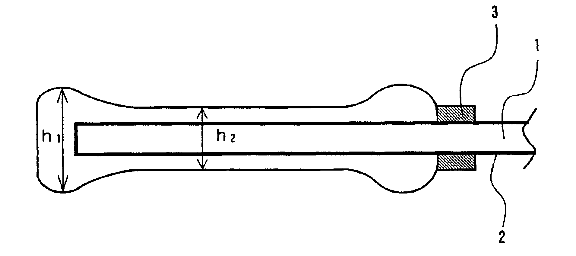
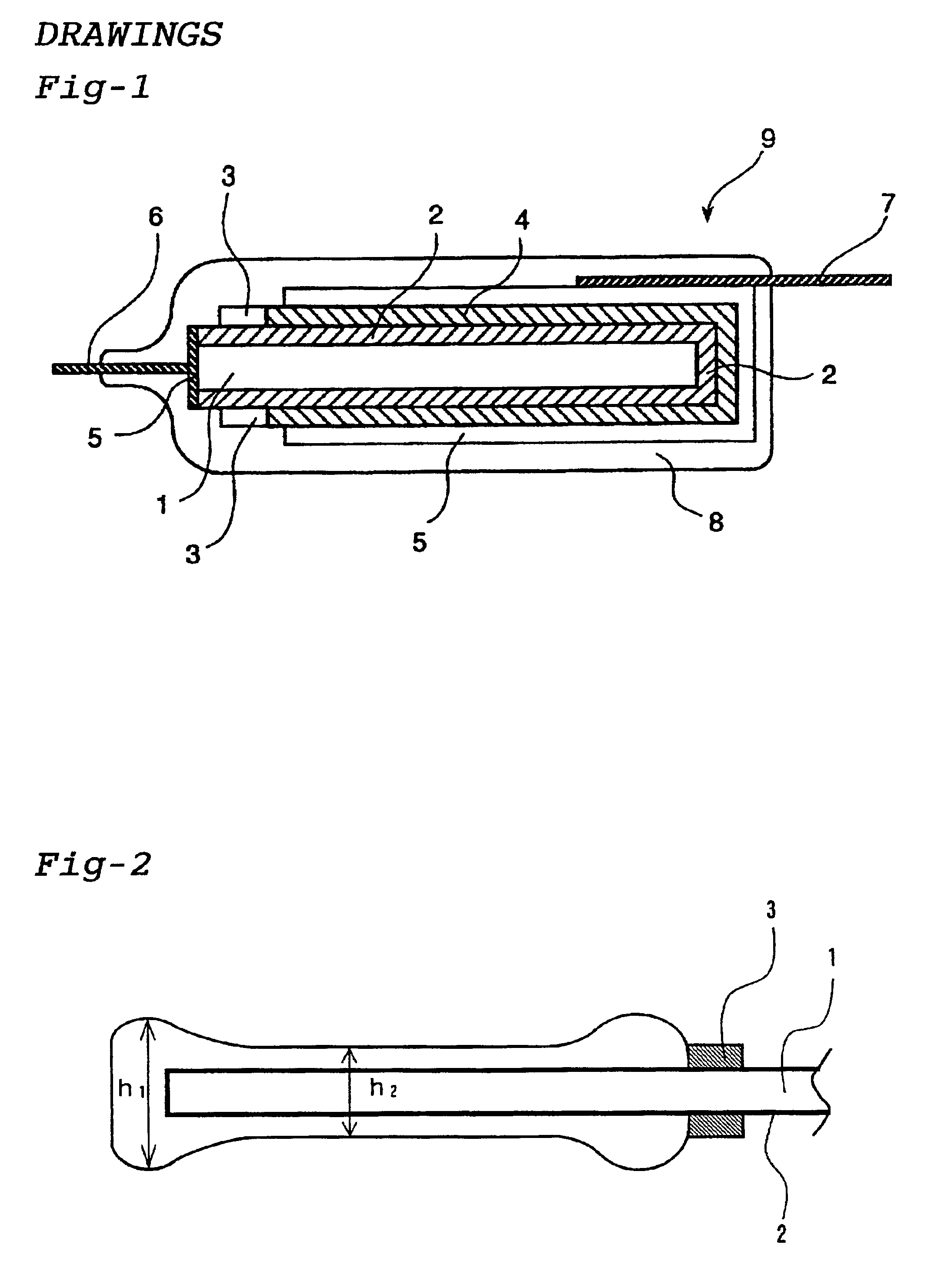
The thickness of the overhanging part of the solid electrolyte layer was measured in the same manner as in Example 1 and found to be 250 μm, the thickness of the constriction portion at the center part was 200 μm, and the difference (h1-h2) in the film thickness was 50 μm.
These capacitor devices were evaluated on the properties in the same manner as in Example 1. The results obtained are shown in Tables 1 and 2.
example 3
30 Units of capacitors were fabricated in the same manner as in Example 1 except that pyrrole was used in place of 3,4-ethylenedioxythiophene in Example 1 and at this time, the pyrrole solution impregnated was dried at 3° C. for 5 minutes and thereafter, an oxidizing agent solution was impregnated to perform the polymerization at 5° C. for 10 minutes.
The thickness of the overhanging part of the solid electrolyte layer was measured in the same manner as in Example 1 and found to be 280 μm, the thickness of the constriction portion at the center part was 210 μm, and the difference (h1-h2) in the film thickness was 70 μm.
These capacitor devices were evaluated on the properties in the same manner as in Example 1. The results obtained are shown in Tables 1 and 2.
PUM
| Property | Measurement | Unit |
|---|---|---|
| Temperature | aaaaa | aaaaa |
| Time | aaaaa | aaaaa |
| Time | aaaaa | aaaaa |
Abstract
Description
Claims
Application Information