

Organic polymeric antireflective coatings deposited by chemical vapor deposition
a technology of organic polymeric antireflective coatings and chemical vapor deposition, which is applied in the direction of photosensitive materials, separation processes, instruments, etc., can solve the problems of increasing inefficiencies of spin coating processes, inadequate coating uniformity across the wafer, and limited performance, so as to minimize negative effects, reduce overall waste, and minimize solvent waste
- Summary
- Abstract
- Description
- Claims
- Application Information
AI Technical Summary
Benefits of technology
Problems solved by technology
Method used
Image

Examples
example 1
Synthesis of [2.2](1,4)-Naphthalenophane
A mixture of 1,4-dimethylnaphthalene (12.5 g, 0.08 mol), N-bromosuccinimide (30.6 g, 0.17 mol—a brominating agent), and benzoyl peroxide (0.4 g—a catalyst) in carbon tetrachloride (70 ml) was stirred and refluxed for 1 hour. The reaction mixture was cooled to room temperature, and the precipitate was filtered and washed with carbon tetrachloride. A suspension was formed by stirring this solid with water (500 ml) for 45 min. followed by filtering, washing with water, and drying. Recrystallization from ethyl acetate furnished pure 1,4-bis(bromomethyl)naphthalene in 86% yield and with a melting point of 188° C.
Next, 1,4-bis(bromomethyl)naphthalene was extracted (Soxhlet) into a refluxing solution of sodium iodide (15 g) in acetone (250 ml) for 24 hrs. The solvent was evaporated on a rotary evaporator until the overall reaction mixture volume was around 50 ml, and then the mixture was poured into 150 ml of water. Sodium thiosulfate was added until...
example 2
Synthesis of 4-Substituted-[2.2](1,4)-Naphthalenophane
A mixture of anhydrous, finely powdered aluminum chloride (0.004 mol) was stirred in dichloromethane (100 ml), followed by slow addition of the corresponding aryl or heteroaryl acid chloride (0.0037 mol) over a period of 30 min. Next, [2.2](1,4)-naphthalenophane (0.003 mol) was slowly added. The reaction mixture was stirred and refluxed for 5-9 hrs. The mixture was cooled to room temperature and poured over a mixture of ice water and 20 ml of concentrated hydrochloric acid. The mixture was poured into a separatory funnel. The organic layer was washed with dilute sodium hydroxide solution, then washed with water, and finally dried over anhydrous magnesium sulfate. Finally, the organic layer was evaporated on a rotary evaporator to isolate pure 4-substituted-[2.2](1,4)-naphthalenophane (see Structure B) in a 63-89% yield. The respective structures of the compounds were confirmed by IR, NMR, and elemental analyses.
wherein, R is C6H...
example 3
Synthesis of [2.2](2,6)-Naphthalenophane
A mixture of 2,6-dimethylnaphthalene (12.5 g, 0.08 mol), N-bromosuccinimide (30.6 g, 0.17 mol), and benzoyl peroxide (0.4 g) in carbon tetrachloride (70 ml) was stirred and refluxed for 1 hour. The reaction mixture was cooled to room temperature and the precipitate was filtered and then washed with carbon tetrachloride. A suspension was formed by stirring this solid with water (500 ml) for 45 min. followed by filtering, washing with water, and drying. Recrystallization from ethyl acetate furnished pure 2,6-bis(bromomethyl)naphthalene.
Next, 2,6-bis(bromomethyl)naphthalene was extracted (Soxhlet) into a refluxing solution of sodium iodide (15 g) in acetone (250 ml) for 24 hrs. The solvent was evaporated on a rotary evaporator until the overall reaction mixture volume was around 50 ml, and then the mixture was poured into 150 ml of water. Sodium thiosulfate was added until the color changed to white, followed by filtering and drying. Recrystalliz...
PUM
| Property | Measurement | Unit |
|---|---|---|
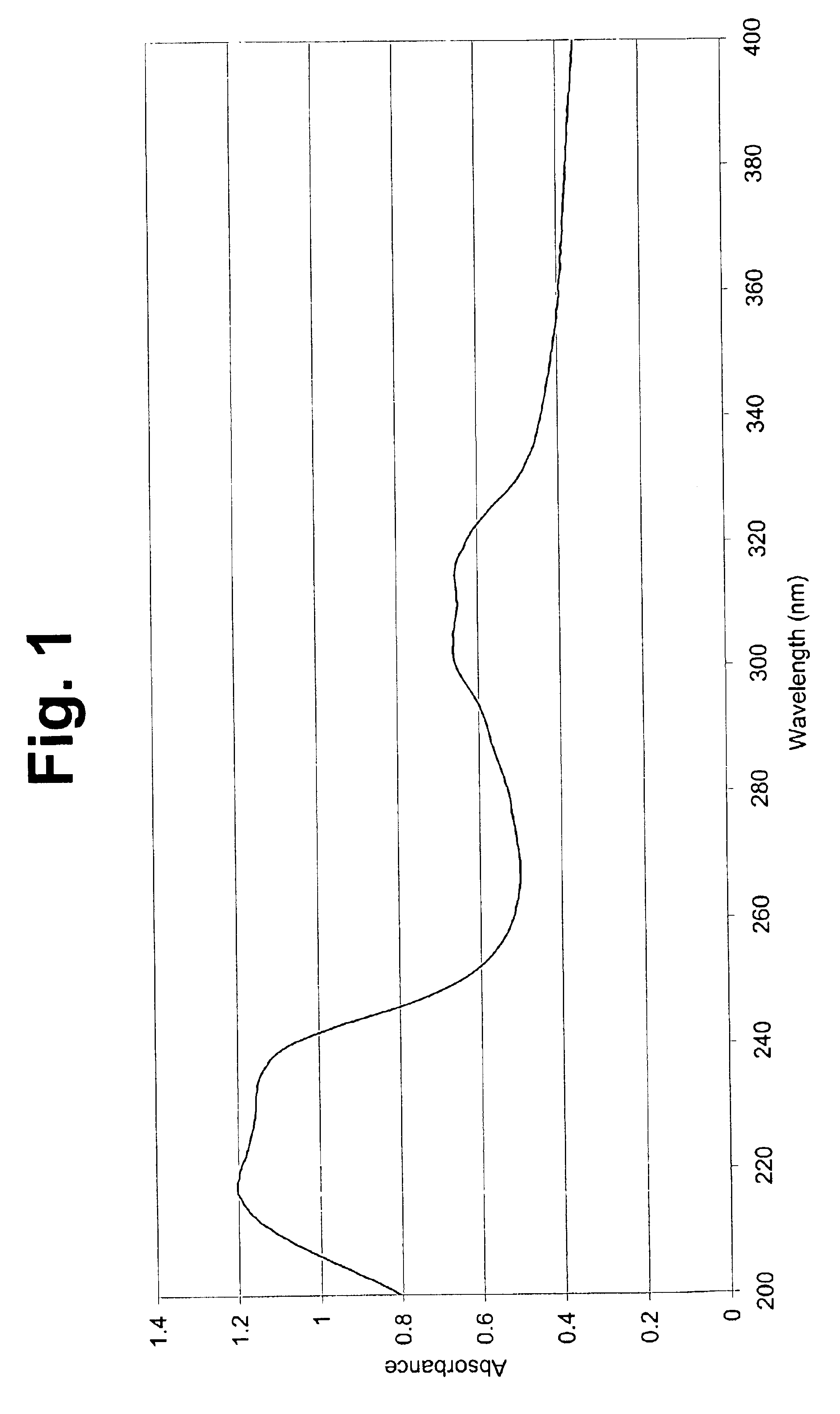
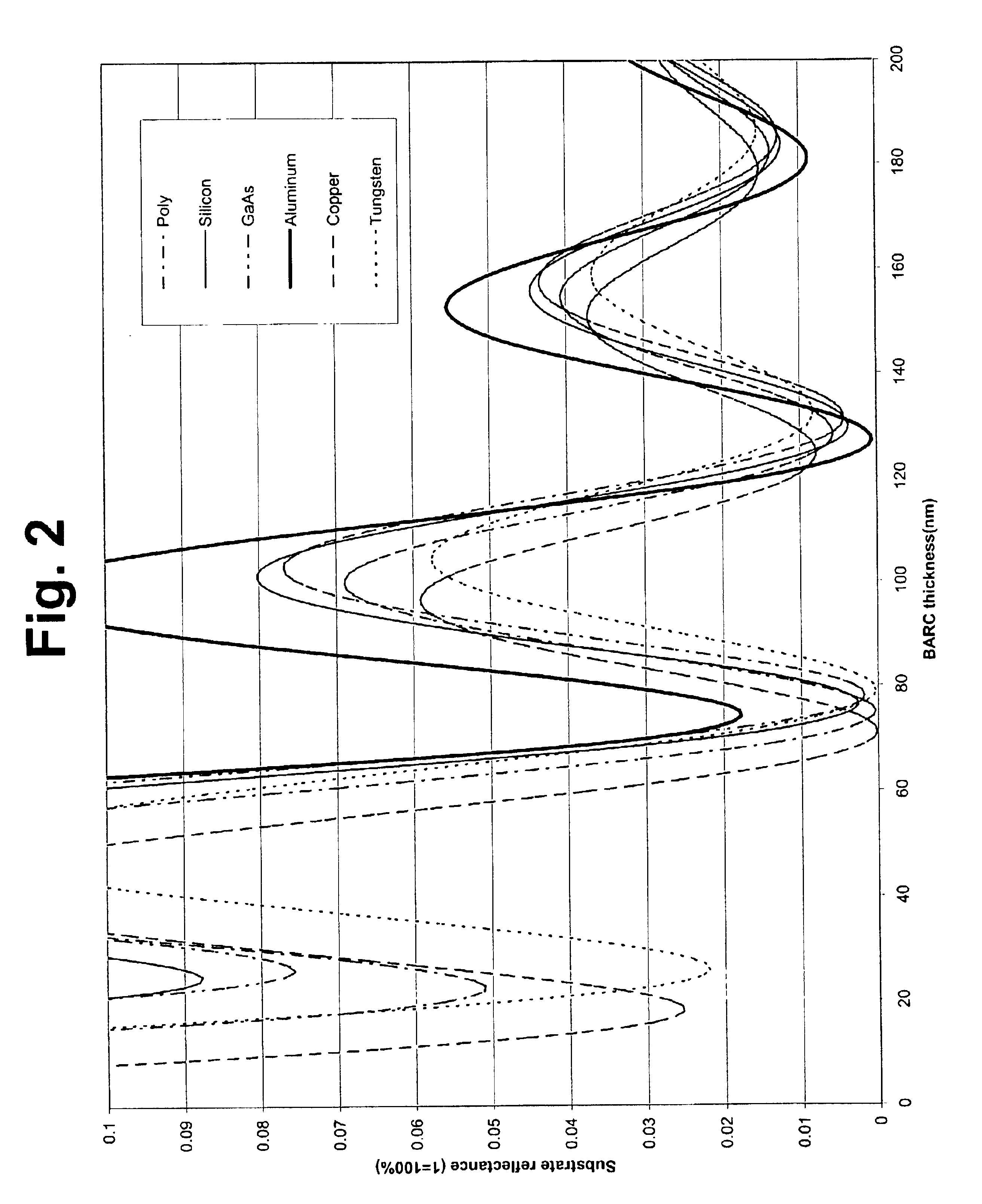
| reflectivity | aaaaa | aaaaa |
| thickness | aaaaa | aaaaa |
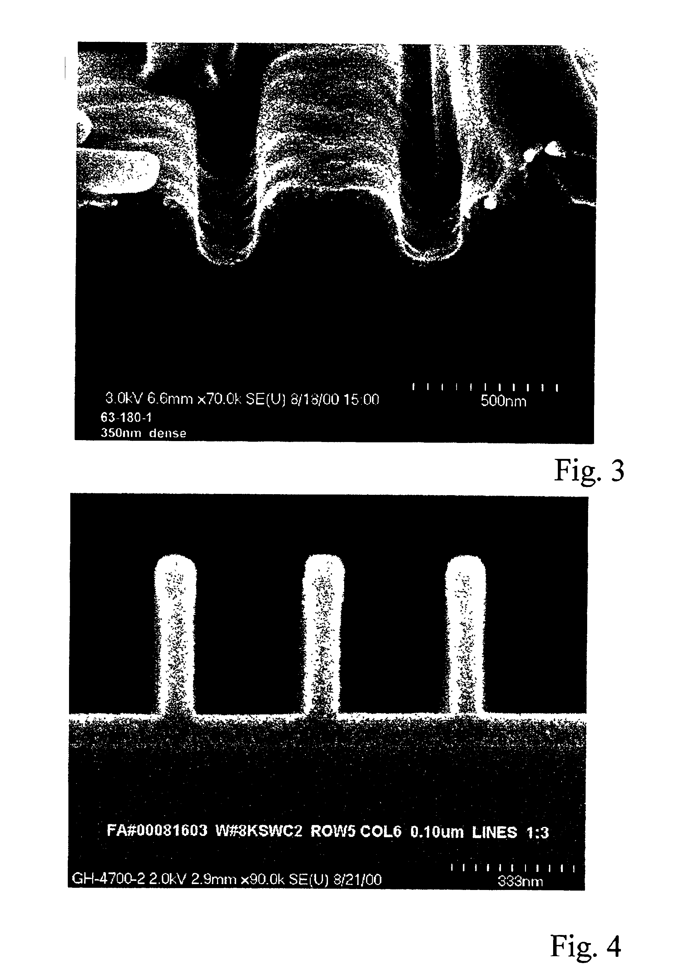
| size | aaaaa | aaaaa |
Abstract
Description
Claims
Application Information