Stimulation device for sleep apnea prevention, detection and treatment

a technology of sleep apnea and stimulation device, which is applied in the field of therapy for patients, can solve the problems of mechanical blockage of the airway, obstructive sleep apnea, and reduction of airway muscle tone, and achieve the effects of increasing cardiac output, increasing blood oxygen concentration, and increasing pacing ra

a technology of sleep apnea and stimulation device, which is applied in the field of therapy for patients, can solve the problems of mechanical blockage of the airway, obstructive sleep apnea, and reduction of airway muscle tone, and achieve the effects of increasing cardiac output, increasing blood oxygen concentration, and increasing pacing ra

US6928324B2Inactive Publication Date: 2005-08-09PACESETTER INC

Image

  • Stimulation device for sleep apnea prevention, detection and treatment
  • Stimulation device for sleep apnea prevention, detection and treatment
  • Stimulation device for sleep apnea prevention, detection and treatment

Examples


Embodiment Construction

)

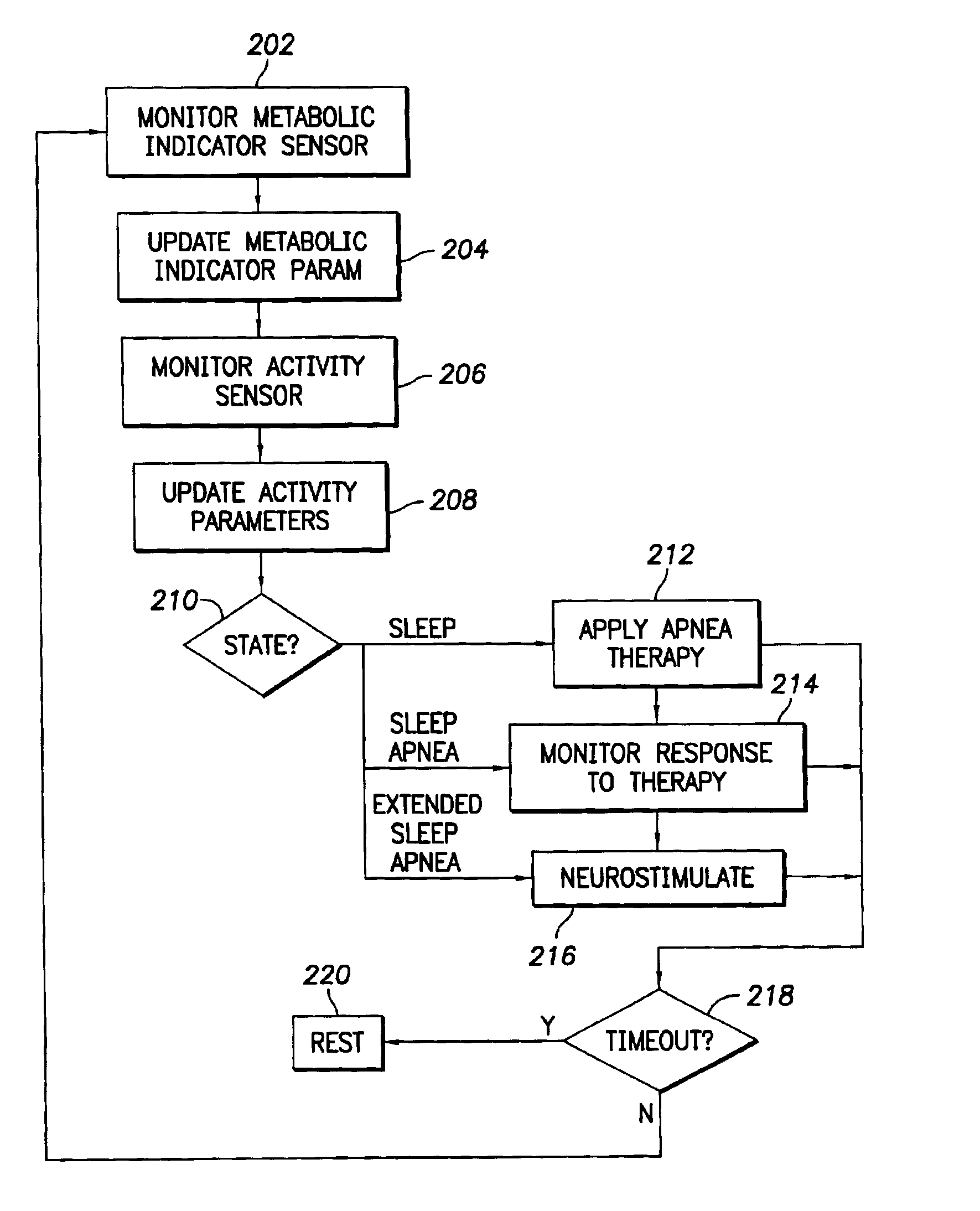
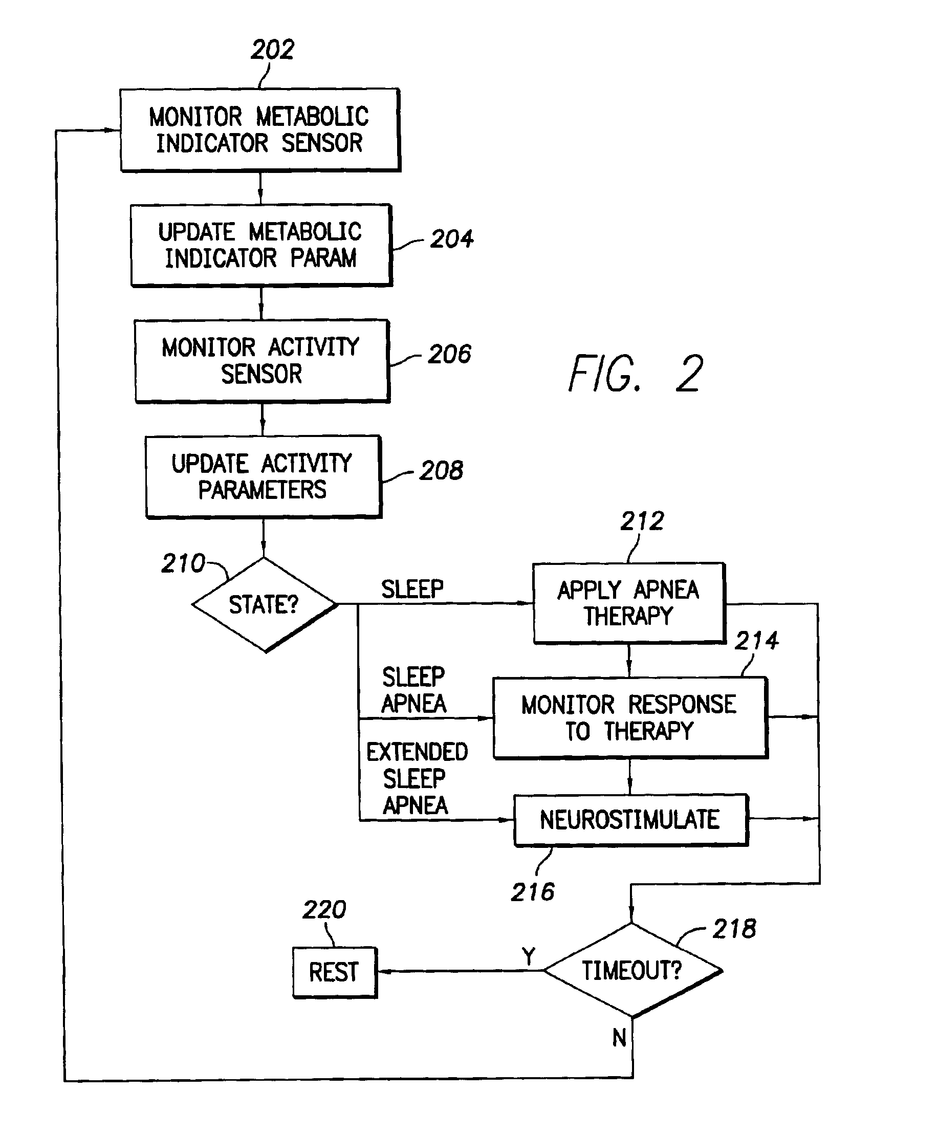
[0040]The following describes the best mode presently contemplated for practicing the invention. The description is not to be taken in a limiting sense but is set forth to convey the general principles of operation and structure of the illustrative embodiments. The issued claims define the invention scope. In the following description, like numerals or reference designators refer to like parts or elements throughout.

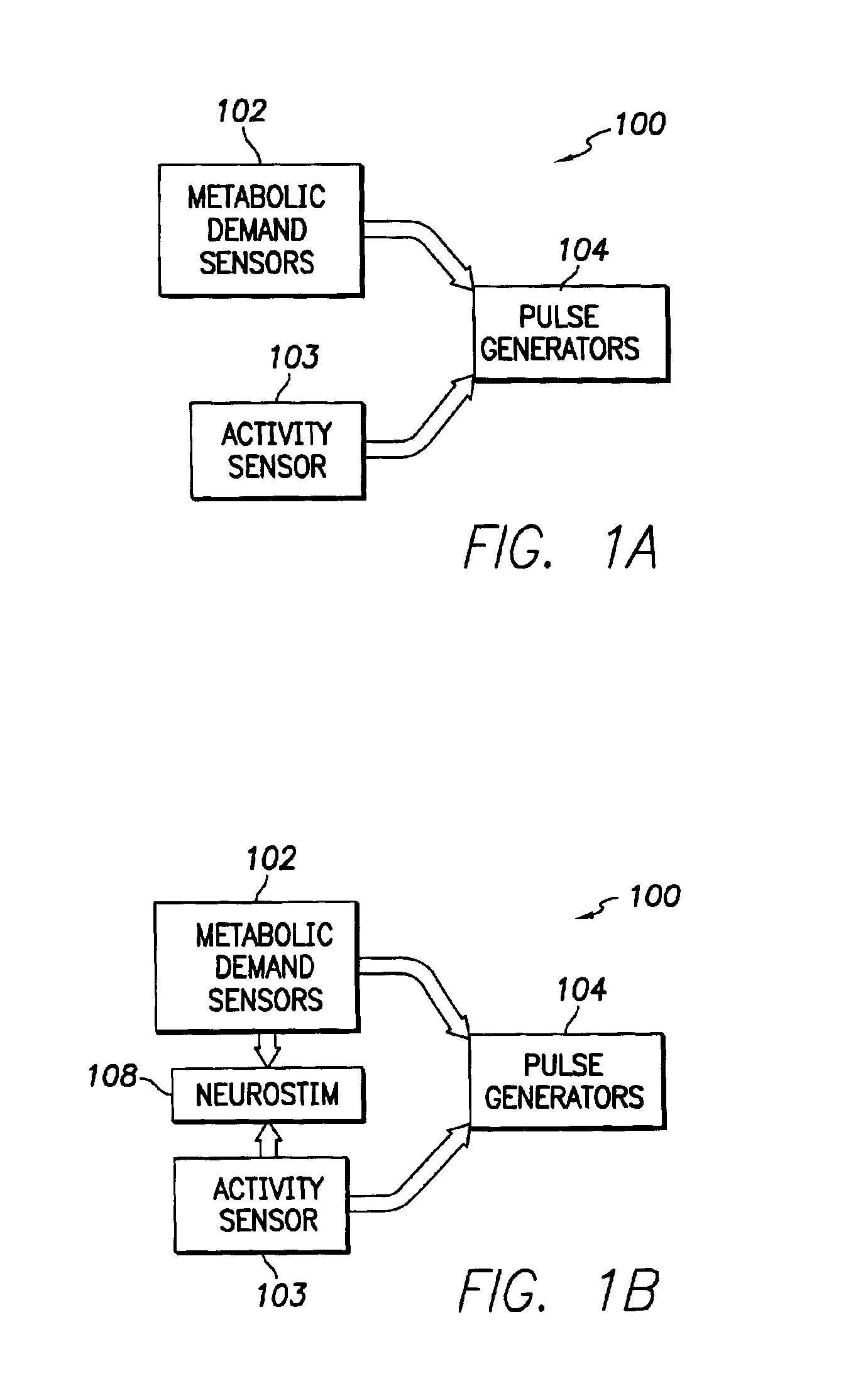
[0041]Referring to FIG. 1, a highly schematic block diagram depicts an example of an implantable cardiac stimulation device 100 that includes a metabolic demand sensor 102, and activity sensor 103, and one or more pulse generators 104. The physiological sensor 102 is capable of sensing a metabolic demand parameter such as respiration, minute ventilation, cardiac conductivity, blood oxygen concentration, stroke volume, and others. Still other suitable parameters include parameters based on sensing of cardiac electrical signals, the parameters including QT interval, evoke...


PUM


Abstract

An implantable cardiac stimulation device comprises a metabolic demand sensor, an activity sensor, and one or more pulse generators. The metabolic demand sensor and activity sensor can sense metabolic demand and physical activity parameters, respectively. The pulse generators can generate cardiac pacing pulses with timing based on a comparison of the metabolic demand and physical activity parameters. The timed cardiac pacing pulses can prevent a sleep apnea condition.

Description

CROSS-REFERENCE TO RELATED APPLICATIONS[0001]This application is related to copending, commonly-assigned U.S. patent application Ser. No. 10 / 077,053, titled SLEEP APNEA THERAPY DEVICE USING DYNAMIC OVERDRIVE PACING; and U.S. patent application Ser. No. 10 / 077,660, tilted CARDIAC STIMULATION DEVICE INCLUDING SLEEP APNEA PREVENTION AND TREATMENT; both applications filed concurrently herewith.FIELD OF THE INVENTION[0002]The present invention relates to techniques for providing therapy to patients who suffer from sleep apnea.BACKGROUND OF THE INVENTION[0003]Sleep apnea is the cessation of breathing for a short time while sleeping. Sleep apnea has multiple classifications based on source of dysfunction. Obstructive sleep apnea results from mechanical blockage of the airway, for example due to weight of fatty neck tissue compressing the trachea. Central sleep apnea results from neurological dysfunction. Mixed sleep apnea has a combination of mechanical and neurological cause.[0004]Upper a...

Claims


Application Information

Patent Timeline
09 Aug 2005
Publication
US6928324B2
IPC
A61N1/365; A61N1/36
CPC
A61N1/36585; A61N1/3601; A61N1/36542; A61N1/36557
Inventors
PARK, EULJOON; KOH, STEVE