
Pattern formation method

a formation method and pattern technology, applied in the field of pattern formation methods, can solve the problems of difficult dissolution of base polymers in alkaline developers, and achieve the effect of suppressing resolution and preventing the reduction of contrast in solubility

Inactive Publication Date: 2005-09-27
PANASONIC CORP
View PDF19 Cites 21 Cited by
  • Summary
  • Abstract
  • Description
  • Claims
  • Application Information

AI Technical Summary

Benefits of technology

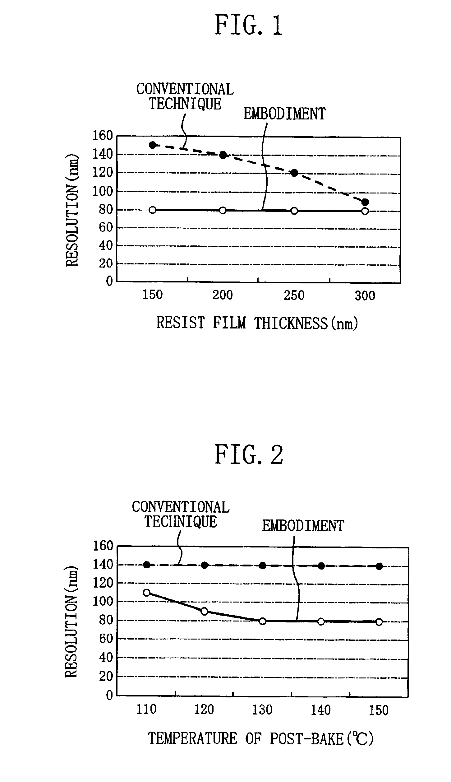
[0019]In consideration of the aforementioned conventional problems, an object of the invention is providing a pattern formation method in which lowering of resolution can be suppressed by preventing lowering of contrast in solubility even when a resist film has a thickness smaller than 250 nm.
[0022]According to the pattern formation method of this invention, since at least one electron attractive group is introduced into a meta-position of an aromatic ring included in the counter anion of the acid generator, the acid generator can attain a higher hydrophobic property than a conventional acid generator, and hence, the dissolution inhibiting property given to the base polymer by the acid generator can be increased. Therefore, in a region of an unexposed portion of the resist film in contact with an exposed portion, namely, in a region that is slightly exposed, the base polymer is difficult to dissolve in an alkaline developer. As a result, the contrast between the solubility of the unexposed portion and the solubility of the exposed portion can be increased, so as to improve the resolution of the resist film.
[0024]Since the dissolution inhibiting property given to the base polymer by the acid generator is increased in the pattern formation method of this invention, the solubility in an alkaline developer of the exposed portion of the resist film is also disadvantageously lowered. However, when the resist film is subjected to post-exposure-bake at a temperature of 120° C. through 150° C., the solubility in an alkaline developer of the exposed portion of the resist film can be improved.

Problems solved by technology

Therefore, in a region of an unexposed portion of the resist film in contact with an exposed portion, namely, in a region that is slightly exposed, the base polymer is difficult to dissolve in an alkaline developer.

Method used


Image

  • Pattern formation method
  • Pattern formation method
  • Pattern formation method

Examples


synthesis example 3

of Base Polymer

[0125]Now, an example of the synthesis of poly(p-hydroxystyrene / styrene / 1-adamantyl acrylate), that is, the base polymer represented by general formula (6), will be described.

[0126]First, p-hydroxystyrene (87.7 g), styrene (18.7 g) and 1-adamantyl acrylate (18.6 g) are dissolved in isopropanol (400 mL). Thereafter, 2,2′-azobis(methyl 2-methylpropyonate) (trade name: V-601; manufactured by Wako Pure Chemical Industries, Ltd.) (10.0 g) is added to the resultant solution, and a reaction is caused in a stream of nitrogen at a temperature of 80° C. for 6 hours.

[0127]Next, the resultant reaction product is poured into water (10 L) so as to precipitate, and the thus obtained deposit crystal is filtered and dried under reduced pressure to give a slightly brown powder crystal (100 g) of poly(p-hydroxystyrene / styrene / 1-adamantyl acrylate). The composition ratios in this copolymer measured by the 13C-NMR method are 73:18:9 (=a p-hydroxystyrene unit: a styrene unit: a 1-adamantyl...

synthesis example 1

of Acid Generator

[0128]Now, an example of the synthesis of diphenyl-2,4,6-trimethylphenylsulfonium pentafluorobenzenesulfonate, that is, the compound represented by general formula (1), will be described.

[0129](First stage)

[0130]First, diphenyl sulfoxide (24.0 g) is dissolved in tetrahydrofuran (600 mL) in an atmosphere of nitrogen, and chlorotrimethylsilane (31.5 g) is poured into the resultant solution. Then, a Grignard reagent obtained by a general method from 2-bromomesitylene (60 g) and magnesium (4.70 g) is added dropwise to the resultant solution cooled with ice, and a reaction is caused for 3 hours at the same temperature. After completing the reaction, a 24% hydrobromic acid aqueous solution (480 mL) is added dropwise to the reaction solution at a temperature of 0 through 5° C. Thereafter, toluene (600 mL) is poured into the resultant solution and the solution is stirred. Next, the stirred reaction solution is separated, and an organic layer is extracted with a 12% hydrobro...

synthesis example 2

of Acid Generator

[0137]Now, an example of the synthesis of triphenylsulfonium pentafluorobenzenesulfonate, that is, the compound represented by general formula (1), will be described.

[0138](First stage)

[0139]A white crystal (20.2 g) of triphenylsulfonium bromide is obtained through a reaction and a post-treatment the same as those of the first stage of the synthesis example 1 of the acid generator except that 2-bromomethylene used at the first stage of the synthesis example 1 is replaced with bromobenzene (47.3 g). The characteristics of the obtained white crystal are as follows:

[0140]Melting point: 288 through 290° C.

[0141]1HNMR (CDCl3) δ ppm: 7.72-7.89 (I5H, m, Ar-H)

[0142](Second stage)

[0143]The triphenylsulfonium bromide (17.2 g) obtained at the first stage and a salt of tetramethylammonium pentafluorobenzenesulfonate (20.9 g; 0.065 mol) are used for performing a reaction and a post-treatment the same as those of the second stage of the synthesis example 1, to give a colorless vi...


PUM

PropertyMeasurementUnit
thicknessaaaaaaaaaa
wavelengthaaaaaaaaaa

Abstract

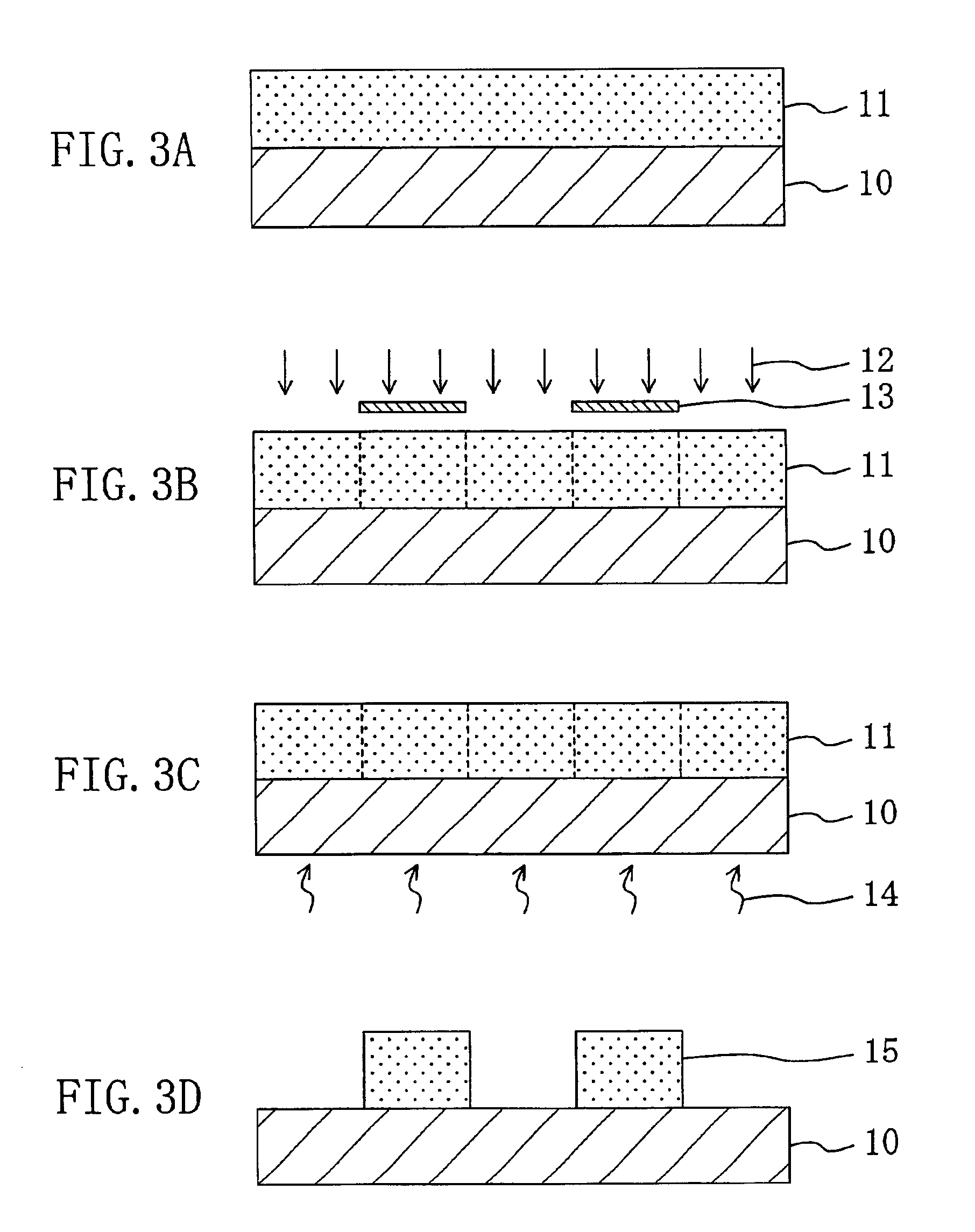
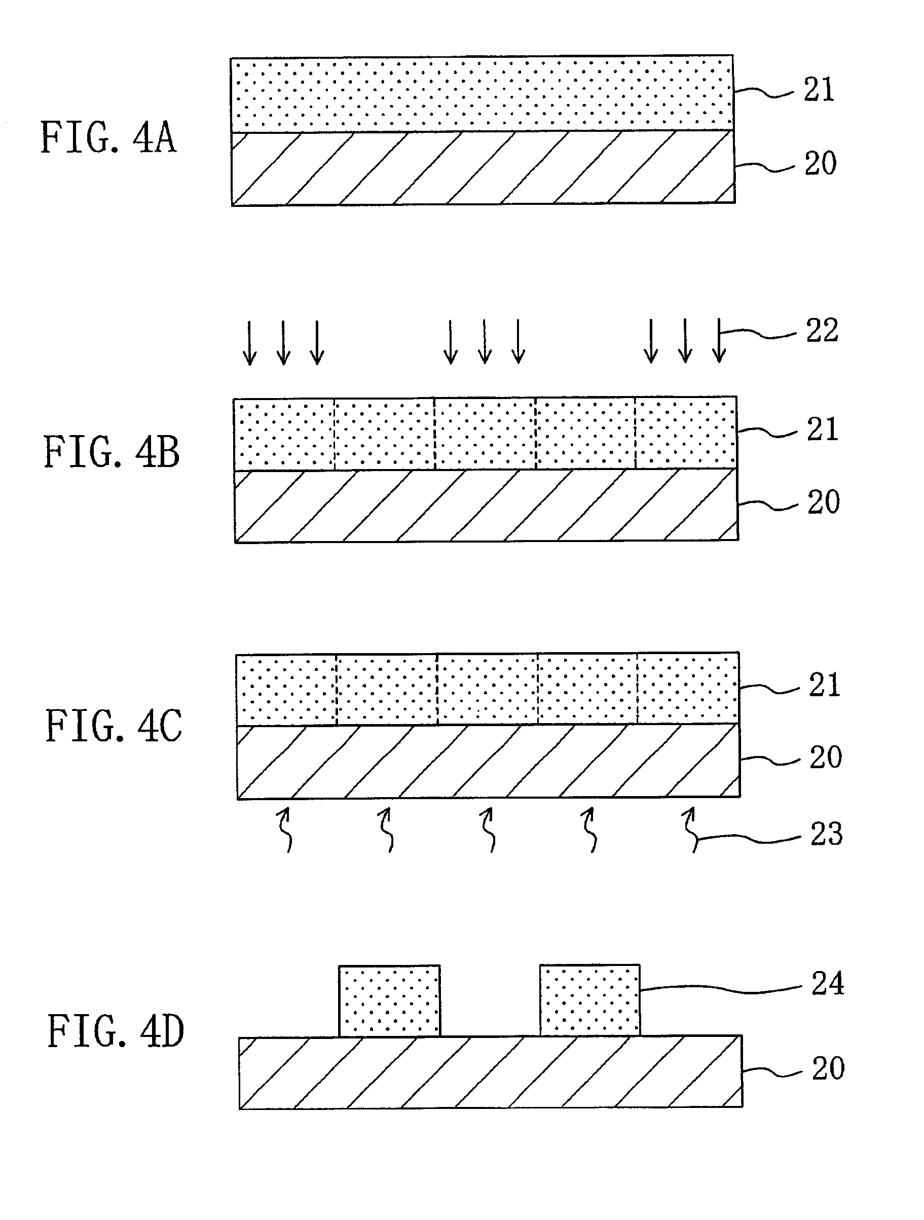
A resist film with a thickness of 250 nm or less is formed on a semiconductor substrate from a positive chemically amplified resist material including a base polymer whose solubility in an alkaline developer is changed by a function of an acid and an acid generator that has at least one electron attractive group introduced into a meta-position of an aromatic ring included in a counter action and generates an acid through irradiation with electron beams. The resist film is subjected to pattern exposure by irradiating with electron beams or extreme UV of a wavelength of a 1 nm through 30 nm band. The resist film is developed after the pattern exposure, thereby forming a resist pattern.

Description

BACKGROUND OF THE INVENTION[0001]The present invention relates to a pattern formation method for use in fabrication of semiconductor integrated circuit devices and the like, and more particularly, it relates to a method for forming a resist pattern by selectively irradiating a resist film of a positive chemically amplified resist material with electron beams or extreme UV of a wavelength of a 1 nm through 30 nm band.[0002]In accordance with recently increased degrees of density and integration of semiconductor integrated circuits, the wavelength of exposing light used in photolithography has been more and more shortened. Recently, extreme UV (of a wavelength of a 300 nm band or shorter) and krF excimer laser (of a wavelength of a 248 nm band) are practically used, and ArF excimer laser (of a wavelength of a 193 nm band) will be put to practical use in the near future. However, these exposing light cannot be used in very fine processing with a design rule of 100 nm or less because of...

Claims


Application Information

Patent Timeline
Patent Type & Authority Patents(United States)
IPC IPC(8): G03F7/039G03F7/004
CPCG03F7/0045G03F7/0392
Inventor ENDO, MASAYUKISASAGO, MASARU
Owner PANASONIC CORP
Learn More