Separation media, multiple electrospray nozzle system and method

a fluidic system and electrospray technology, applied in the direction of electrostatic separation, particle separator tube details, fluorescence/phosphorescence, etc., can solve the problems of inability to use an lc column with these small particles, limited lc pump availability, etc., to increase the mass spectral sensitivity of microfluidics, increase the useful fluid flow rate range, and increase the flow rate

Inactive Publication Date: 2005-10-18
ADVION
View PDF158 Cites 8 Cited by
  • Summary
  • Abstract
  • Description
  • Claims
  • Application Information

AI Technical Summary

Benefits of technology

[0060]The use of multiple nozzles for electrospray of fluid from the same fluid stream extends the useful flow rate range of microchip-based electrospray devices. Thus, fluids may be introduced to the multiple electrospray device at higher flow rates as the total fluid flow is split between all of the nozzles. For example, by using 10 nozzles per fluid channel, the total flow can be 10 times higher than when using only one nozzle per fluid channel. Likewise, by using 100 nozzles per fluid channel, the total flow can be 100 times higher than when using only one nozzle per fluid channel. The fabrication methods used to form these electrospray nozzles allow for multiple nozzles to be easily combined with a single fluid stream channel greatly extending the useful fluid flow rate range and increasing the mass spectral sensitivity for microfluidic devices.
[0061]The use of polymer monoliths contained within the through-substrate channels of this electrospray device incorporating multiple nozzels is a significant advan...

Problems solved by technology

However, the use of such small particles results in many technical challenges.
One of these technical challenges is the backpressure resulting from pushing the mobile phase through each of these columns.
Most commercially available LC pumps are limited to operating pressures less than 400 bar and thus using an LC column with these small particles is not feasible.
One challenge to using miniaturized separation techniques is detection of the small peak volumes and a limited number of detectors that can accommodate these small volumes.
Currently, anisotropic RIE techniques for glass substrates are limited to etching features that are 20 μm or less in depth.
This work shows rectangular 5 μm by 5 μm width by 10 μm in depth posts and stated that deeper structures were difficult to achieve.
In electrokinetically driven flow systems, large variations in the cross-sectional area along the length of a separation channel can create flow restrictions that result in bubble formation in the separation channel.
Since the fluid flowing through the separation channel functions as the source and carrier of the mobile solvated ions, formation of a bubble in a separation channel will result in the disruption of the electroosmotic flow.
A liquid jet extends from the tip of the Taylor cone and becomes unstable and generates charged-droplets.
When the repulsion force of the solvated ions is not sufficient to overcome the surface tension of the fluid exiting the tip of the capillary, large poorly charged droplets are formed.
Fluid droplets are produced when the electrical potential difference applied between a conducti...

Method used


Image

  • Separation media, multiple electrospray nozzle system and method
  • Separation media, multiple electrospray nozzle system and method
  • Separation media, multiple electrospray nozzle system and method

Examples


Embodiment Construction

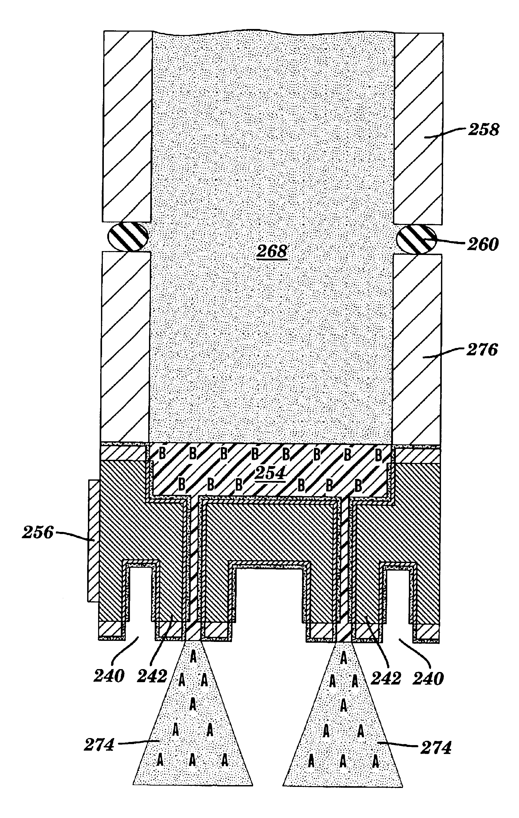
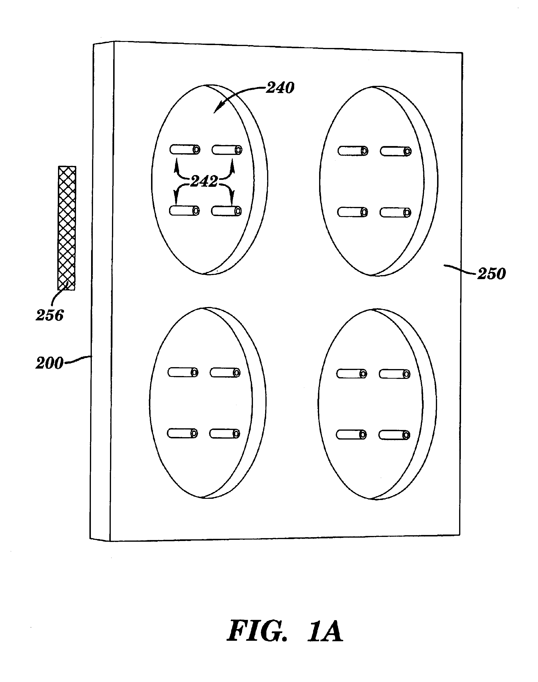
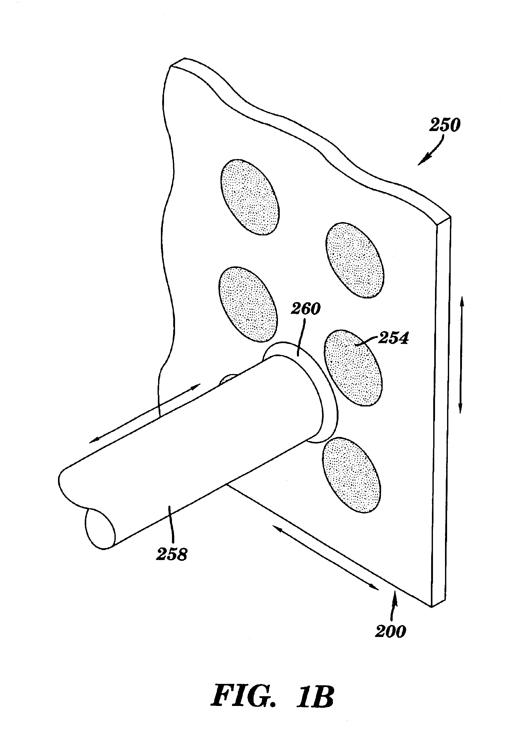
[0129]Control of the electric field at the tip of a nozzle is an important component for successful generation of an electrospray for microfluidic microchip-based systems. This invention provides sufficient control and definition of the electric field in and around a nozzle microfabricated from a monolithic silicon substrate for the formation of multiple electrospray plumes from closely positioned nozzles. The present nozzle system is fabricated using Micro-ElectroMechanical System (“MEMS”) fabrication technologies designed to micromachine 3-dimensional features from a silicon substrate. MEMS technology, in particular, deep reactive ion etching (“DRIE”), enables etching of the small vertical features required for the formation of micrometer dimension surfaces in the form of a nozzle for successful nanoelectrospray of fluids. Insulating layers of silicon dioxide and silicon nitride are also used for independent application of an electric field surrounding the nozzle, preferably by ap...


PUM

PropertyMeasurementUnit
Electrical resistanceaaaaaaaaaa

Abstract

A microfabricated silicon chip with a separation material, such as in situ prepared porous polymer monoliths in its microchannels is disclosed. The polymer monoliths are liquid-permeable and serve as microcolumns for liquid chromatography, which are prepared by in situ radical polymerization of a mixture containing vinyl monomers and solvents (porogen) in the microchannels. A method and system are disclosed to generate one or more electrospray plumes from one or more nozzles that provide an ion intensity as measured by a mass spectrometer that is approximately proportional to the number of electrospray plumes formed for analyses contained within the fluid. A plurality of electrospray devices can be used in the form of an array of miniaturized separate electrospray devices for the purpose of generating multiple electrospray plumes from multiple nozzles for the same fluid for analysis. This invention dramatically increases the sensitivity of microchip electrospray devices compared to prior disclosed systems and methods. The silicon chip having the packed microchannels disclosed herein finds application in coupling with mass spectrometry for sample analysis. Also disclosed is a separation block having multiple through-substrate channels filled with a separation material such as polymer monolith which can be stacked in multiple blocks for sequential two-dimensional chromatographic separation and integrated with the electrospray device.

Description

[0001]This application is a division of U.S. patent application Ser. No. 09 / 764,698, filed Jan. 18, 2001 now U.S. Pat. No. 6,596,988.[0002]This application claims the benefit of U.S. Provisional Patent Application Ser. No. 60 / 176,605, filed Jan. 18, 2000, which is herein incorporated by reference in its entirety.FIELD OF THE INVENTION[0003]The present invention relates generally to an integrated miniaturized fluidic system fabricated using Micro-ElectroMechanical System (MEMS) technology, particularly to an integrated monolithic microfabricated device capable of generating multiple sprays from a single fluid stream and a separation material, preferably a porous monolithic polymer bed, for chromatographic separations.BACKGROUND OF THE INVENTION[0004]New trends in drug discovery and development are creating new demands on analytical techniques. For example, combinatorial chemistry is often employed to discover new lead compounds, or to create variations of a lead compound. Combinatori...

Claims


Application Information

Patent Timeline
IPC IPC(8): G01N27/447G01N30/00G01N30/60G01N30/46H01J49/02H01J49/04G01N30/52G01N30/28G01N30/72G01N27/62B01D15/08B01D57/02B01D59/44B01J20/281B01J20/283B01J20/285B03C5/00B05B5/043G01N1/10G01N21/33G01N21/53G01N21/64G01N30/74G01N30/88G01N37/00H01J49/00H01J49/10
CPCB01J20/261B01J20/267B01J20/281B01J20/285G01N27/44717G01N30/463G01N30/466G01N30/467G01N30/48G01N30/6095G01N30/7266H01J49/0018H01J49/167B01J2220/54B01J2220/82G01N2030/285G01N2030/528B01J20/283B01J20/103
Inventor CORSO, THOMAS N.SCHULTZ, GARY A.PROSSER, SIMON J.HUANG, XIAN
Owner ADVION
Why Eureka
Try Eureka