Emissions reduction system for an internal combustion engine

a technology of emission reduction and internal combustion engine, which is applied in the direction of machines/engines, mechanical equipment, and non-fuel substance addition to fuel, etc., can solve the problems of inability to leave excessive amounts of water in the intake path, lack of adequate control means, and inherent dangers of human exposure, so as to improve performance, reduce harmful emissions, and increase fuel efficiency

Inactive Publication Date: 2006-03-21
CONTEGO MEDICAL INC
View PDF13 Cites 49 Cited by
  • Summary
  • Abstract
  • Description
  • Claims
  • Application Information

AI Technical Summary

Benefits of technology

[0018]It is a general objective of this invention to provide a novel method and system for controlling exhaust gas emissions by controlling the temperature and humidity levels in the intake air stream of an internal c...

Problems solved by technology

Unfortunately, he was apparently unaware of the inherent dangers of human exposure to radioactive elements.
His method lacks adequate control means and is capable of leaving excessive amounts of water in an intake path after engine shutdown.
Their vapor device would present numerous problems, both in its installation and subsequent maintenance or repair because of its internal placement and its inadequate control parameters.
Additionally, its piezoelectric vibrator would be considerably vulnerable to rapid deterioration due to its intermittent exposure to air.
This method produces a hydrogen-enriched fuel but the end result is a fuel that is less efficient, therefore more costly to use.
His device is very limited in scope and effectiveness under varying conditions.
The device raises many questions, such as absence of means to control water vapor, water movement issues in a moving vehicle, evaporation issues allowing excess water vapor to flow into the intake manifold of a warm engine after shutdown, etc.
Their system offers no continuity of benefits, but rather is a method for water disposal in rare instances.
These methods are not only limited because of their inability to precisely detect and provide means for optimal engine operation but also are incapable of metering a continuously optimized volumetric ratio of water in the final fuel/air charge.
Spray or steam injection systems also could damage the turbine blades in a turbocharged engine unless injected downstream from the compressor.
Injecting hot steam also has a disadvantage in that it doesn't have as much expansion capability in the power stroke as cool vapor has.
In the event that one of the prior art systems did not completely cut off the water supply before engine shutdown, an accumulation of water in the intake manifold or combustion chamber could result in corrosive and/or mechanical damage to internal engine parts on subsequent start-up or over a protracted period of time.
Although this problem is generally recognized as critical to the effective operation of a water injection system, none of the prior art adequately demonstrates fail-safe measures to assure minimal humidity in an intake manifold at engine shutdown.
However, only one of them offers a means for the removal of min...

Method used


Image

  • Emissions reduction system for an internal combustion engine
  • Emissions reduction system for an internal combustion engine
  • Emissions reduction system for an internal combustion engine

Examples


Embodiment Construction

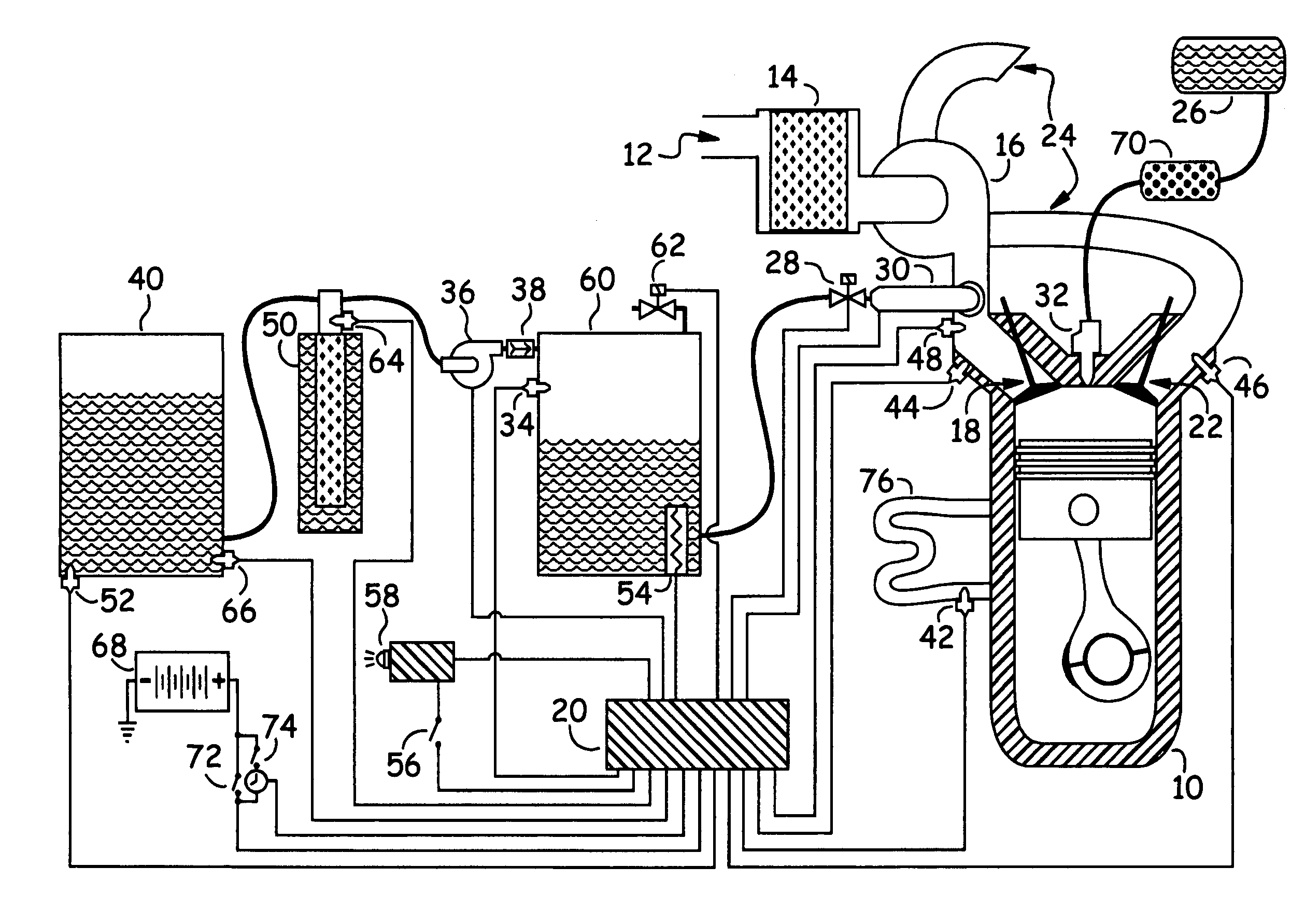
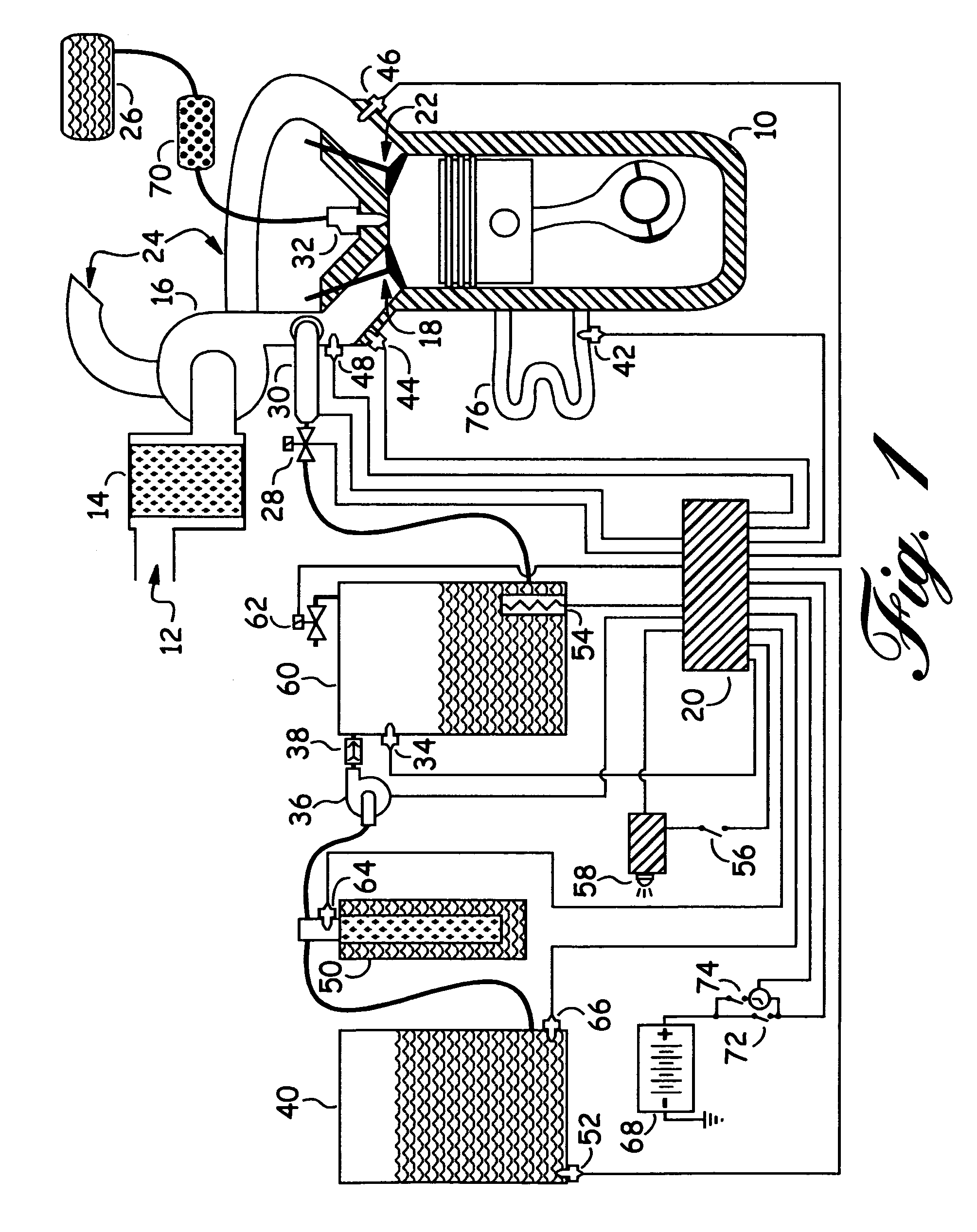
[0043]The FIG. 1 drawing depicts a piston engine 10, equipped with an air intake housing 12, containing an air filtering device 14, connected to a turbocharger compressor 16 that sends compressed air to an air intake port 18, having an exhaust port 22 and an exhaust system path 24 for the dispersion of combustion gases expelled by said engine 10. Said engine 10 is started by switching power to engine ignition system 72, connected to a DC power supply 68. An electronic control module 20 is powered on at engine start-up and begins to monitor all system sensors: (42, 44, 46, 48, 52 and 66). Simultaneously, as fuel enters said engine 10 through a fuel delivery system 32, said fuel passes from a fuel supply tank 26 and through a catalytic fuel conditioning unit 70 before being consumed by said engine 10. When said engine 10 is under a load, a thermal sensor 46 near said exhaust port 22 signals a valve 62 to close and a valve 28 to open and a pressurizing means 36 transfers water from sai...


PUM


Abstract

A dual system for overall engine emissions control, including prevention of excessive formation of nitrogen oxides and carbon compounds 1) by cooling and humidifying intake air and 2) by restructuring and modifying hydrocarbon fuels, resulting in a more complete combustion, a significant reduction of the latent heat of combustion and increased combustion potency. The invention utilizes one or more ultrasonic devices to create an aqueous vapor from an ultra-pure water supply, said vapor varying in quantity according to engine size and load, having electronic sensors and controls for precision switching, metering and delivery. Simultaneously, while humidifying the intake air, the hydrocarbon fuel is passed from a fuel supply through a catalytic reactor to restructure the hydrocarbon molecules into a more homogeneous, more combustible and cleaner-burning fuel. Thus equipped, said internal combustion engine can be run as a fuel conserving, low emissions prime mover.

Description

REFERENCES CITED[0001]DocumentInventorIssue DateClassificationU.S. Pat. No.DuclouxOctober 1930123 / 31,777,554U.S. Pat. No.LuertzingNovember 1938210 / 2052,136,170U.S. Pat. No.StephensonFebruary 1941123 / 1222,231,605U.S. Pat. No.MoriyaOctober 1962261 / 723,059,910U.S. Pat. No.GinsburghMay 1968317 / 23,383,560U.S. Pat. No.YoshimineAugust 1971317 / 2623,597,668U.S. Pat. No.SerruysFebruary 1975123 / 25A3,866,579U.S. Pat. No.Williams, et al.October 1975123 / 25K3,911,871U.S. Pat. No.MinozaOctober 197548 / 180C3,915,669U.S. Pat. No.Kosaka, et al.May 197823 / 288L4,088,450U.S. Pat. No.LindbergOctober 1984123 / 34,476,817U.S. Pat. No.WalkerDecember 1987123 / 1A4,715,325U.S. Pat. No.HarkFebruary 1989204 / 182.54,808,287U.S. Pat. No.O'Neill et al.October 1990123 / 2544,960,080U.S. Pat. No.MarlowDecember 1992204 / 1685,167,782U.S. Pat. No.Nowlin et al.November 1995210 / 1905,464,532U.S. Pat. No.Yoshihara et al.June 1996123 / 25C5,522,349U.S. Pat. No.WrightDecember 199644 / 3215,580,359U.S. Pat. No.O'DonnellSeptember 1997123 / 25...

Claims


Application Information

Patent Timeline
IPC IPC(8): F02B43/10
CPCF02B47/02F02B51/02F02M25/0224F02M25/0225F02M25/025Y02T10/121Y02T10/126Y02T10/12
Inventor MCFARLAND, STEVEJONES, WILBUR
Owner CONTEGO MEDICAL INC
Why Eureka
Try Eureka