Metal film and metal film-coated member, metal oxide film and metal oxide film-coated member, thin film forming apparatus and thin film forming method for producing metal film and metal oxide film

a metal film and film coating technology, applied in the direction of chemical vapor deposition coating, vacuum evaporation coating, sputtering coating, etc., can solve the problems of difficult to achieve high reflectivity, metal film such as thin silver film formed by vacuum deposition is extremely vulnerable to the influence of the environment, and metal film may be blackened and peeling off, etc., to achieve good crystal orientation, low surface roughness, and high quality

Active Publication Date: 2006-04-25
KYOCERA OPTEC
View PDF4 Cites 19 Cited by
  • Summary
  • Abstract
  • Description
  • Claims
  • Application Information

AI Technical Summary

Benefits of technology

[0012]A main object of the present invention is to provide a metal film of high quality single crystal that has very low surface roughness and very good crystal orientation and a metal film-coated member.
[0013]Another object of the present invention is to provide a dense metal oxide film that includes less oxygen defects and almost no voids therein, and a metal oxide film-coated member.
[0014]A still another object of the present invention is to provide a metal film that can be formed even on the surface of a substrate of low durable temperature and has an excellent bonding characteristic with the substrate, a metal film-coated member, a metal oxide film and a metal oxide film-coated member.

Problems solved by technology

Meanwhile a metal film such as thin silver film formed by vacuum deposition is extremely vulnerable to the influence of the environment, and is subjected to white clouding caused by an oxide film formed on the surface thereof in about 24 hours when left in the atmosphere as it has been vapor-deposited, and the metal film may be blackened and peel off in the worst case.
Also when the metal film does not sufficiently adhere to the base material, water may infiltrate into the interface with the base material and cause erosion.
However, since the metal films obtained by these methods have rough surfaces with the crystal being poorly oriented, it has been difficult to achieve high reflectivity.
There have also been such problems as the white clouding of the metal film surface due to oxidation and weak bonding with the substrate surface as described previously.
However, since sufficient reaction energy cannot be obtained simply by accelerating oxidation in the case of vacuum deposition process in which chromium oxide is evaporated and deposited in oxygen gas atmosphere, the film tends to become deficient of oxygen resulting in insufficient resistivity.
In the case of ion plating and sputtering processes, oxidizing reaction is accelerated but the substrate is attacked by carrier gas or the like thus making it difficult to control the composition.
When a plastic material is used as the substrate, sufficient bonding of a film thereto cannot be achieved by the prior art method, and it has been difficult to form an insulation film of practical value.
Moreover, since the substrate cannot be maintained at a desired low temperature, materials that can be used in the substrate have been limited.
The thin film forming methods of the prior art described above have such a problem that a metal oxide film having a high packing density cannot be obtained.
Such a low packing density (in other words abundance of voids in the film) affects the optical characteristics of the film, and therefore the metal oxide film of the prior art has a low and unsatisfactory reflectivity in the region of visible light.

Method used


Image

  • Metal film and metal film-coated member, metal oxide film and metal oxide film-coated member, thin film forming apparatus and thin film forming method for producing metal film and metal oxide film
  • Metal film and metal film-coated member, metal oxide film and metal oxide film-coated member, thin film forming apparatus and thin film forming method for producing metal film and metal oxide film
  • Metal film and metal film-coated member, metal oxide film and metal oxide film-coated member, thin film forming apparatus and thin film forming method for producing metal film and metal oxide film

Examples


example 1

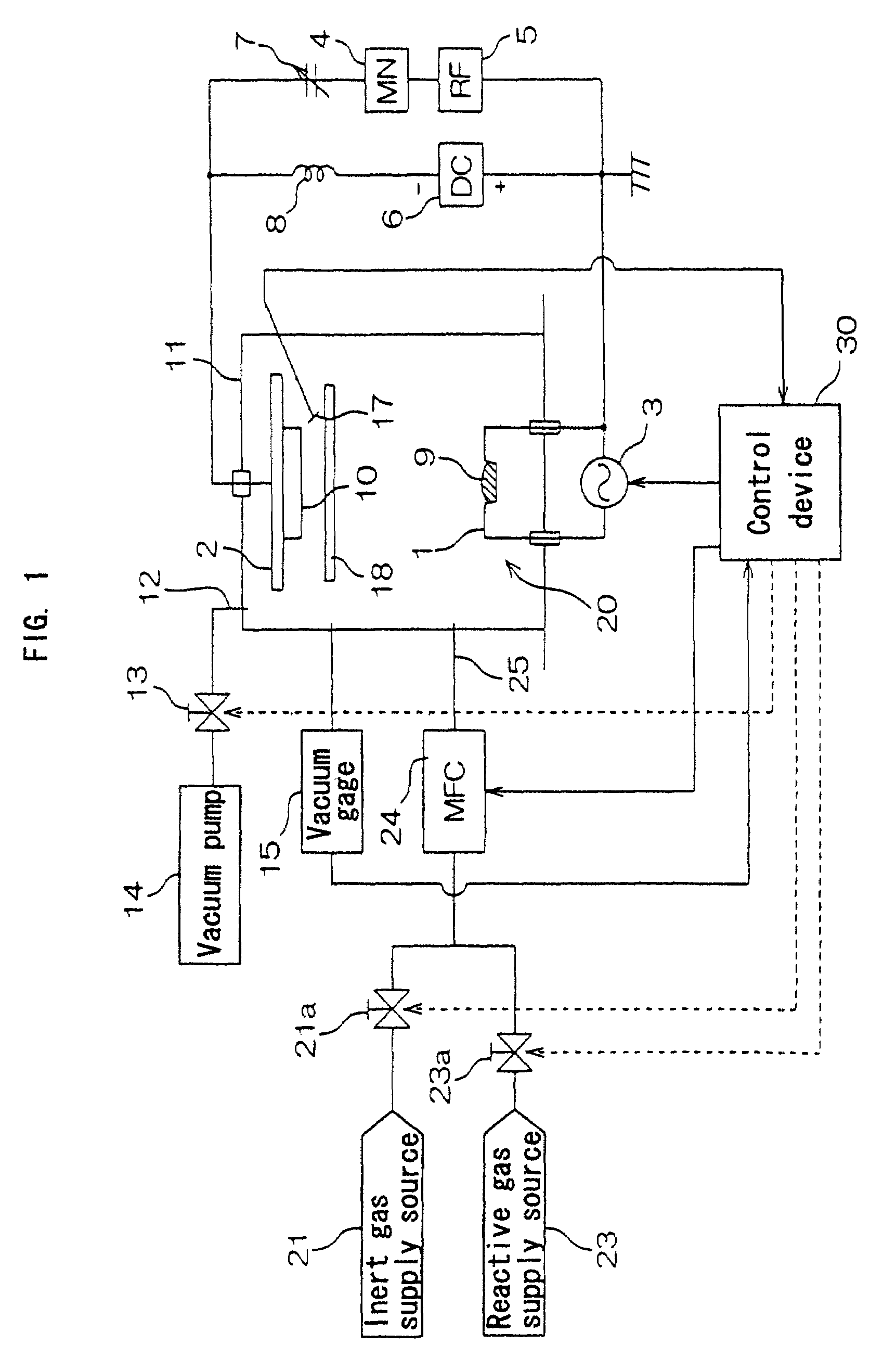
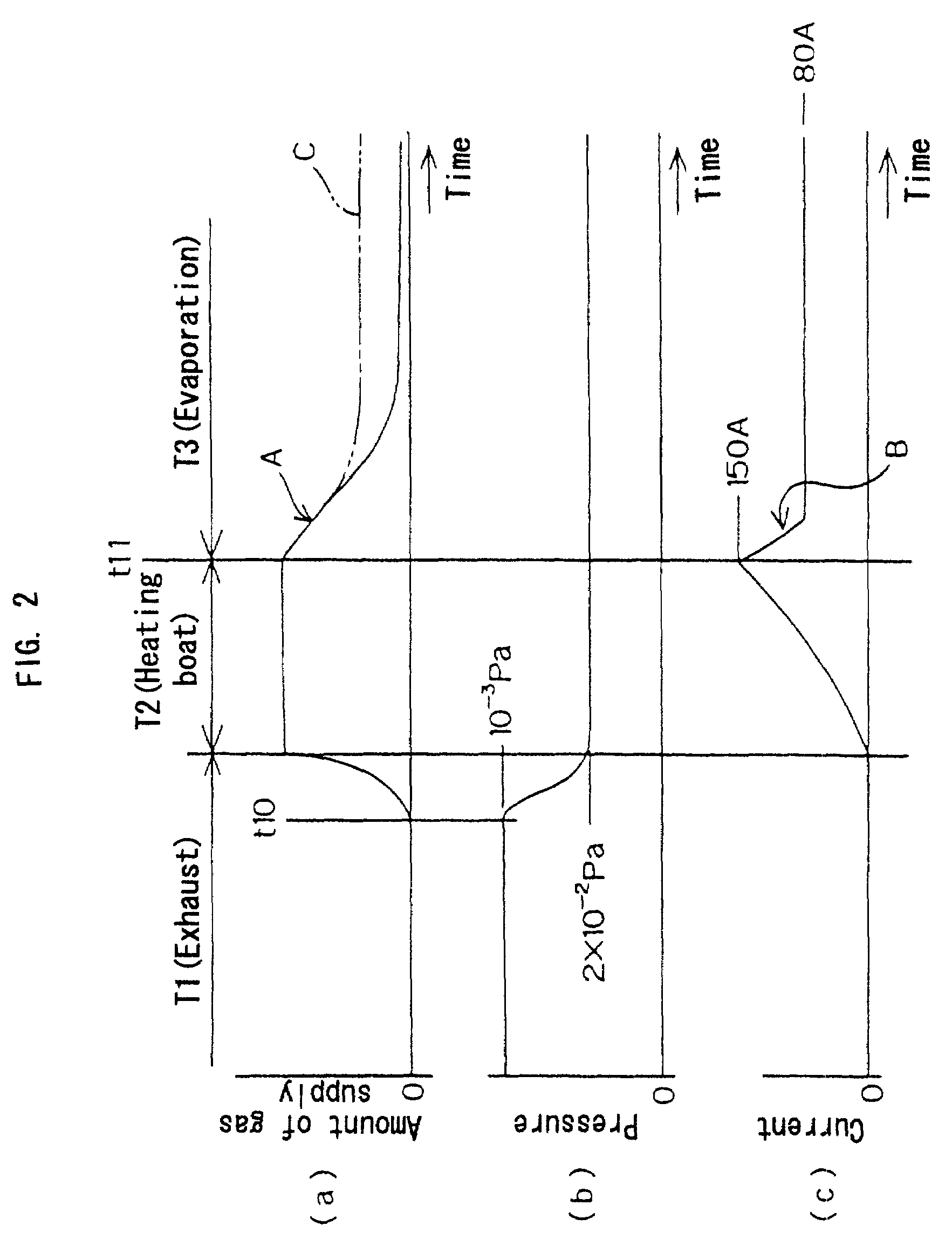
[0198]A silver film was formed in the process shown in FIG. 2 by using the thin film forming apparatus shown in FIG. 1, under the following conditions.

[0199]Substrate 10: A glass sheet 3 mm in thickness.

[0200]Evaporation material 9: Silver.

[0201]Gas introduced into the chamber 11: Argon gas.

[0202]Power supplied from the high frequency power source 5 to the substrate holding section 2: 85 mW / cm2 (power supplied per unit area of the substrate holding section 2) at frequency 13.56 MHz.

[0203]DC voltage source 6: Cathode connected to the substrate holding section 2 and anode connected to the boat 1.

[0204]Voltage applied by the DC voltage source 6 to the substrate holding section 2: 230 V.

[0205]Chamber 11: Electrically floated without grounding.

[0206]Rate of forming the metal film: 18 Å / second.

[0207](a) Early stage of forming metal film (period T2 shown in FIG. 2)

Pressure in the chamber 11: Constant at 2×10⁻² Pa.

Current supplied from the heating power source 3 to the boat 1: 280 A (at end...

example 2

(Formation of Chromium Oxide)

[0234]A chromium oxide film was formed in the process shown in FIG. 2 by using the thin film forming apparatus shown in FIG. 1, under the following conditions.

[0235]Substrate 10: A glass sheet 3 mm in thickness.

[0236]Evaporation material 9: Chromium (purity 99.9%).

[0237]Gas introduced into the chamber 11: Argon gas and oxygen gas.

[0238]Power supplied from the high frequency power source 5 to the substrate holding section 2: 85 mW / cm2 (power supplied per unit area of the substrate holding section 2) at frequency 13.56 MHz.

[0239]DC voltage source 6: Cathode connected to the substrate holding section 2 and anode connected to the boat 1.

[0240]Voltage applied by the DC voltage source 6 to the substrate holding section 2: 230 V.

[0241]Chamber 11: Electrically floated without grounding.

[0242]Rate of forming the metal oxide film: 15 Å / second.

(A) Early Stage of Forming Metal Oxide Film (Period T2 Shown in FIG. 2)

Pressure in the chamber 11: Constant at 2×10⁻² Pa.

Cu...

example 3

(Formation of Titanium Oxide Film)

[0257]Titanium oxide film was formed on the surface of a substrate so that an equation: n×d=3λ0 / 4 (n is refractive index of titanium oxide, d is thickness of titanium oxide film and λ0=580 nm) is satisfied , in the same manner as in Example 2, except for using titanium as the evaporation material and changing the output power of the high frequency power source 5 to 78 mW / cm2.

1. Transmittance and Reflectivity

[0258]Transmittance and reflectivity of the titanium oxide film obtained in Example 3 were measured with a photometer (spectrophotometer U-4000 manufactured by Hitachi Limited). The results are shown in FIG. 22. As shown in FIG. 22, transmittance was almost equal to the theoretical value of pure titanium oxide. Theoretical values were the refractive index shown in the list of fundamental physical properties (published by Kyoritsu Publishing Co., Ltd. on May 15, 1972) and the value of reflectivity calculated from the value of coating material give...


PUM

PropertyMeasurementUnit
arithmetic mean roughnessaaaaaaaaaa
reflectivityaaaaaaaaaa
incident anglesaaaaaaaaaa

Abstract

The metal film of the present invention is a dense film of a single crystal that has very low surface roughness and very good crystal orientation because an arithmetic mean roughness of the surface is not larger than 2 nm and a (111) peak intensity of X-ray diffraction is not less than 20 times the sum of all other peaks. Also the metal oxide film of the present invention is a dense film that includes less oxygen defects and almost no voids therein because a content of a non-oxidized metal is not higher than 1 mole % of a metal component that constitutes the metal oxide and a packing density is 0.98 or higher.

Description

FIELD OF THE INVENTION[0001]The present invention relates to a metal film and a metal film-coated member used for optical coating film or the like, a metal oxide film and a metal oxide film-coated member used for optical coating film, insulation film or the like, and a thin film forming apparatus and a thin film forming method preferably employed in the production of the metal film and the metal oxide film.BACKGROUND OF THE INVENTION[0002]Coating of various substrates with metal films has been employed for such applications as decoration, improvement of electric characteristics and optical functions. Such metal films are employed for making use of intrinsic physical properties of the metals such as luster, shade, electric properties and optical properties in accordance to the application, while it is desired that the physical properties remain stable for a long period of time.[0003]In the case of metal films used in optical applications including reflector mirror such as those repre...

Claims


Application Information

Patent Timeline
Patent Type & Authority Patents(United States)
IPC IPC(8): B32B15/04B32B15/20B32B33/00F21V7/00G03B21/28C23C14/00C23C14/08C23C14/10C23C14/14C23C14/32C30B23/02G02B1/10G21K1/06
CPCC23C14/0021C23C14/08C23C14/081C23C14/083C23C14/10C23C14/14C23C14/32C30B23/02G02B5/0858G21K1/06C23C14/0694C30B29/02Y10T428/12174G21K2201/06Y10T428/12896Y10T428/12993Y10T428/12736Y10T428/31678
Inventor OKURA, TAKAHIROSHIMIZU, KAZUYATAKEI, MASAKAZU
Owner KYOCERA OPTEC
Why Eureka
Try Eureka