Symmetric, bi-aspheric lens for use in optical fiber collimator assemblies

a collimator and optical fiber technology, applied in the field of symmetric bi-aspheric lenses for optical fiber collimator assemblies, can solve the problems of reducing the amount of required amplification, limiting the amount of information that can be transferred over a communication channel, and high loss of optical power in a fiber system, so as to reduce the strength of curves, improve the efficiency of manufacturing, and increase the index of glasses

Inactive Publication Date: 2006-06-27
EASTMAN KODAK CO
View PDF20 Cites 28 Cited by
  • Summary
  • Abstract
  • Description
  • Claims
  • Application Information

AI Technical Summary

Benefits of technology

[0073]It is an advantage of the invention that higher index glasses be chosen for the lens. A higher index lens reduces the strength of the curves needed to provide a given refracting power, hence making manufacturing easier. It is a further advantage that for a higher index material, a single layer optical coating can cause a significant reduction in the amount of light reflected from the lens surface. This is because the optimal choice for the index of a single-layer antireflection coating is equal to the geometric mean of the refractive indices of the two media on each side of the coating. One of the common coating materials is magnesium fluoride, with a refractive index of 1.38. Hence, magnesium fluoride is optimal for a substrate index of 1.90. The closer the substrate refractive index is to 1.90, the better the performance of the single-layer magnesium fluoride coating.
[0074]It is a further advantage of this invention that the front focal distance “FF” is shorter than a plano-convex collimator lens. A shorter front focal distance aids in mounting an optical filter or other optical component in a photonic device such as a DWDM demultiplexer. Another advantage of this invention is improved manufacturability and reduced alignment sensitivities due to the equal power on both optical surfaces. Referring to FIG. 11, the Gaussian beam 62 is refracted at both optical surfaces 136 and 138 as it passes through lens 134. This reduces the additional insertion loss caused by manufacturing perturbations, such as center thickness, power, irregularity, tilt of the optical surfaces, and decentration of the optical surfaces. Equal power on both surfaces also reduces performance degradations caused by assembly alignment errors such as lens tilt and decentration.
[0075]Yet another advantage of the invention is a reduced scratch-dig specification on the first optical surface of the lens. Any cosmetic imperfections, such as scratches or digs, on the optical surfaces within the Gaussian beam profile will cause a reduction in the coupling efficiency. As the beam size on the optical surface decreases, the acceptable size of the scratch or dig also decreases. The distance from the fiber facet to the first optical surface of the GRIN and plano-convex lens is very small—typically 0.25 mm. Referring to FIG. 1, the beam diameter 14 on the first surface 12 of GRIN lens 16 is typically less than 50 micrometers. This is also true for the...

Problems solved by technology

Loss of optical power in a fiber system is highly undesirable, as it can limit the amount of information that can be transferred over a communication channel or increase the amount of required amplification.
To achieve high coupling efficiency of a beam into an optical fiber, it is not sufficient that the beam be focused onto the fiber with a low amount of aberration.
Although it may be possible to tilt fibers from the optical axis in order to reduce the effective angle between a beam and the optical axis of the fiber, tilting fibers can greatly increase the time and cost of assembling the final optical system.
For systems used to couple light from one fiber to another, it is not desirable to have any apertures that limit the beam and thereby reduce optical power.
The control of the refractive index profile is difficult, since the shape of the profile is controlled only by diffusion of the dopant into the glass.
It is a further disadvantage of gradient index lenses that one of the dopants commonly used...

Method used


Image

  • Symmetric, bi-aspheric lens for use in optical fiber collimator assemblies
  • Symmetric, bi-aspheric lens for use in optical fiber collimator assemblies
  • Symmetric, bi-aspheric lens for use in optical fiber collimator assemblies

Examples


example 1

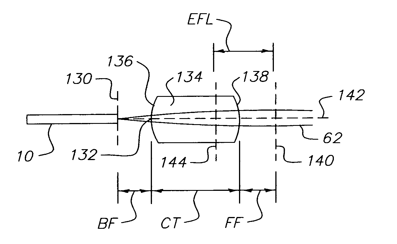
[0083]Example 1 has a symmetric bi-aspheric lens with an effective focal length of 1.944 and an index of refraction=1.50.[0084]Curvature of the first optical surface 1: 0.61903 mm−1 [0085]Conic constant of the first optical surface: k=−2.000878[0086]Center thickness: 1.64 mm.[0087]Curvature of the second optical surface 1: −0.61903 mm−1 [0088]Conic constant of the second optical surface: k=−2.000878[0089]Refractive index at 1550 nm: 1.50[0090]Back focal distance: 1.29 mm[0091]Front focal distance: 1.29 mm[0092]Effective focal length of individual lens: 1.944 mm[0093]Specified entrance pupil diameter: 1.0 mm on the convex surface.[0094]Axial rms wavefront error: 0.001 waves.

example 2

[0095]Example 2 has a symmetric bi-aspheric lens with an effective focal length of 1.944 and an index of refraction=1.60.[0096]Curvature of the first optical surface 1: 0.527295 mm−1 [0097]Conic constant of the first optical surface: k=−2.185689[0098]Center thickness: 1.89 mm.[0099]Curvature of the second optical surface 1: −0.527295 mm−1 [0100]Conic constant of the second optical surface: k=−2.185689[0101]Refractive index at 1550 nm: 1.60[0102]Back focal distance: 1.22 mm[0103]Front focal distance: 1.22 mm[0104]Effective focal length of individual lens: 1.944 mm[0105]Specified entrance pupil diameter: 1.0 mm on the convex surface.[0106]Axial rms wavefront error: 0.001 waves.

example 3

[0107]Example 3 has a symmetric bi-aspheric lens with an effective focal length of 1.944 and an index of refraction=1.70.[0108]Curvature of the first optical surface 1: 0.461127 mm−1 [0109]Conic constant of the first optical surface: k=−2.366173[0110]Center thickness: 2.14 mm.[0111]Curvature of the second optical surface 1: −0.461127 mm−1 [0112]Conic constant of the second optical surface: k=−2.366173[0113]Refractive index at 1550 nm: 1.70[0114]Back focal distance: 1.15 mm[0115]Front focal distance: 1.15 mm[0116]Effective focal length of individual lens: 1.944 mm[0117]Specified entrance pupil diameter: 1.0 mm on the convex surface.[0118]Axial rmis wavefront error: 0.0008 waves.


PUM


Abstract

A fiber optic apparatus comprising a biconvex optical lens having two equivalent aspheric optical surfaces; an optical fiber approximately located at one of a front focal plane and a back focal plane of the optical lens; and a structure positioned relative to the optical lens and the optical fiber, wherein the structure maintains the position of the optical lens relative to the optical fiber.

Description

CROSS REFERENCE TO RELATED APPLICATIONS[0001]Reference is made to commonly assigned co-pending application Ser. No. 10 / 262,233 filed concurrently herewith entitled SYMMETRIC, BI-ASPHERIC LENS FOR USE IN TRANSMISSIVE AND REFLECTIVE OPTICAL FIBER COMPONENTS in the name of Ludington et al.FIELD OF THE INVENTION[0002]This invention relates to an apparatus and method of connecting optical fibers. In particular, it relates to lenses used in optical fiber collimator assemblies, and to the design of such lenses so as to permit improved packaging of optical fibers, lenses, and related components.BACKGROUND OF THE INVENTION[0003]In optical fiber applications, it is often necessary to couple light from one fiber into another. This might be done at a switching device where multiple fibers are brought together or by adding and / or dropping wavelengths in a dense wavelength division multiplexing (DWDM) application. A known way to do this is by directly butting the fibers together. The fibers can a...

Claims


Application Information

Patent Timeline
IPC IPC(8): G02B6/32G02B6/293G02B6/34
CPCG02B6/2937G02B6/327G02B6/32
Inventor LUDINGTON, PAUL D.BIETRY, JOSEPH R.
Owner EASTMAN KODAK CO
Why Eureka
Try Eureka