Electrochromic material

a technology of electrochromic materials and materials, applied in the direction of discharge tube main electrodes, conductors, instruments, etc., can solve the problems of fog factor, inability to meet the needs of use, and the most common use of pdlcs, etc., to improve cyclic durability and chemical stability, reduce degradation problems, and improve durability

Inactive Publication Date: 2008-02-19
NAT RES COUNCIL OF CANADA
View PDF18 Cites 34 Cited by
  • Summary
  • Abstract
  • Description
  • Claims
  • Application Information

AI Technical Summary

Benefits of technology

[0017]Electrochromic materials of the present invention have improved durability and chemical stability, particularly in acidic electrolytes, as well as possessing a desirable neutral color in unbleached (colored) state. Particularly improved electrochromic materials preferably comprise W1−xTaxO3−x / 2 compounds in which x has a value in a range from about 0.2 to about 0.5, with a range of from about 0.25 to about 0.35 being of particular note. Electrochromic materials of the present invention are cathodic materials.
[0022]Pulsed laser deposition (PLD) is a physical vapor deposition technique capable of reproducing target composition with relative ease under appropriate conditions. Therefore, PLD is particularly suitable for preparing thin films of W1−xTaxO3−x / 2 compounds of the present invention. Further, PLD also produces high kinetic and internal energies of the ablated species, which enhances adhesion of the films to substrates. PLD provides better control of film microstructure and morphology, which provides better control of film properties. PLD can usually operate at low processing temperatures without deterioration of film-specific properties, which is excellent for temperature-sensitive substrates. PLD techniques give less time for the tungsten and tantalum to separate into different phases, therefore, a single-phase compound can be maintained. PLD is familiar in the art and has been used in to manufacture films of other metal oxides.
[0027]Any suitable electrolyte may be used, for example, lithium-containing electrolytes or proton-based electrolytes. Proton-based electrolytes are preferred since ionic diffusivity of protons is about two orders of magnitude higher than that of lithium ions, thereby making the coloring / bleaching processes of an electrochromic device much faster.
[0030]Liquid / polymer gel type ion conducting layers are preferred. Solid state layers are prone to having pinholes caused during the deposition of the layer. Such pinholes act as electron channels between the ion conducting layer and the electrochromic layer thereby permitting electrons to flow relatively unimpeded from the electrochromic layer to the transparent conductor layer. Such a condition is known as “shorting” and results in no coloration of the electrochromic layer. Liquid / polymer gel type ion conducting layers rarely suffer from pinholes. A drawback of liquid / polymer gel type ion conducting layers has been the long-term degradation of the electrochromic layer due to contact with liquid / polymer gel type electrolyte. Since the electrochromic materials of the present invention are more durable and chemically stable, this degradation problem is reduced and liquid / polymer gel type ion conducting layers become more desirable.
[0031]Protective layers may be utilized between the ion conducting layer and the electrochromic layer. For example, inorganic films, such as Ta2O5, Sb2O5, or nonporous polymer films, such as ultravioelt light-cured plasticized poly (vinyl alcohol), may be used to coat the electrochromic layer to further protect the electrochromic layer from degradation due to contact with the ion conducting layer. Even though the electrochromic material of the present invention possesses improved cyclic durability and chemical stability and can be used without a protective layer, such protective layers are suggested to further improve durability.

Problems solved by technology

Most uses of PDLCs, however, are confined to privacy applications, where popular uses are found in glass walls for offices, conference rooms, lobbies, and store-fronts.
Liquid crystal technology has not been a commercial success.
The windows are hazy because they scatter rather than absorb light, so there is a fog factor even when the device is in the transparent state.
Also, while liquid crystals work well for interior privacy control, the technology only provides two statuses: clear or opaque, nothing between—it can't be used as a shading device.
In addition, it also tends to be a little expensive for most popular applications, running between $85 and $150 per square foot.
Developing the technology and manufacturing processes has been long and difficult.
The presence of the ions in the electrochromic layer changes its optical properties, causing it to absorb visible light, the result of which is to darken (“unbleach”) the window.
Existing EC devices based on solid state lithium conducting medium, unfortunately, are quite slow.
But for something the size of a window it may take six to 10 minutes to change between coloring and bleaching.
Although inorganic solid-state EC devices can achieve better durability, its response time is relatively slow since the diffusivity of protons and lithium in solid medium is significantly lower than in liquid / polymer gel type media.
However, durability is a significant concern for proton conducting liquid / polymer gel type EC devices, since the solid ion insertion layers (EC and counter electrode layer) can exhibit long-term degradation due to the contact with liquid / polymer gel type electrolytes.
For example, WO3, by far the most common cathodic electrochromic material, has a tendency to slowly dissolve in proton-based electrolyte, which limits its use in proton conducting liquid / polymer gel type electrolytes.

Method used


Image

  • Electrochromic material
  • Electrochromic material
  • Electrochromic material

Examples


example 1

Preparation of W1−xTaxO3−x / 2 Films

[0042]W1−xTaxO3−x / 2 films were deposited by ablating a 90 mm diameter rotating W1−xTaxO3−x / 2 target (Ta0.1W0.9O2.95, 99.9%, from SCI Engineered Materials, Ta0.3W0.7O2.85, 99.95%, and WO3, 99.99% both from Super Conductor Materials) in an advanced deposition chamber (PVD Inc., PLD-3000) by means of a pulsed KrF excimer laser (λ=248 nm, Lambda Physik, LPX-210i), at a repetition rate of 50 Hz. The laser beam was focused down to a spot size of about 4 mm2 on the target surface and the on-target laser beam fluence was adjusted to about 2 to 3 J / cm2. A 25 mm×50 mm×1.1 mm rectangle indium tin oxide (ITO) coated glass (unpolished float glass, SiO2 passivated / ITO coated one surface, Rs=6±2Ω, SiO2 layer thickness: 20-30 nm, ITO layer thickness: 150-200 nm, Delta Technologies, Limited) was used as the substrate for the deposition. To achieve uniform deposition over the entire substrate surface, the laser beam was rastered over the radius of the rotating target...

example 2

Structural Characterization of W1−xTaxO3−x / 2 Films

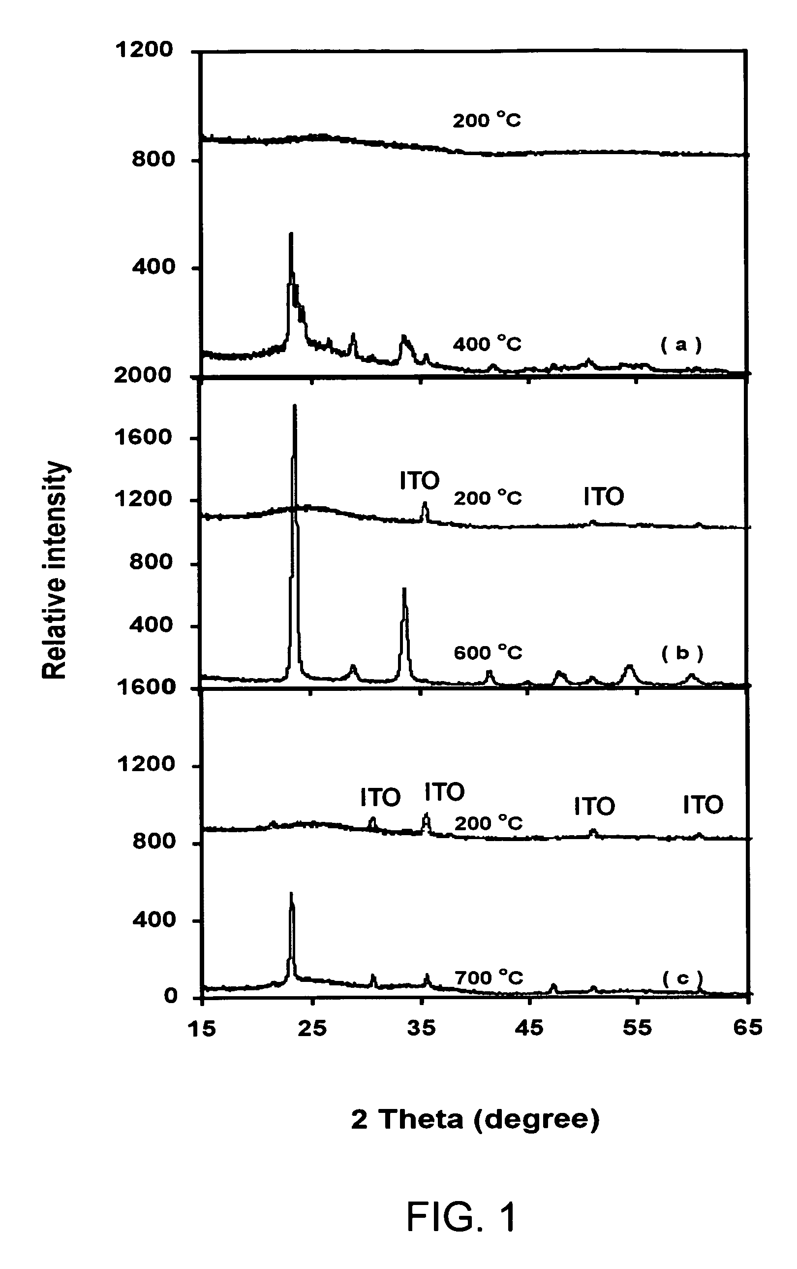
[0044]Structures of the films were examined by X-ray diffraction (XRD, Philips, X-Pert MRD) using monochromatized Cu Kα in the θ0-2θ thin film configuration, where θ0 was fixed at 1°. FIG. 1 shows XRD patterns of WO3, Ta0-1W0.9O2.95 and Ta0.3W0.7O2.85 films deposited in 5.32 Pa of oxygen at 200° C. and their respective crystallization temperatures. At substrate temperatures of 200° C., XRD patterns of all the three materials consist of a diffuse-scattering curve with a broad band centered at 2θ of about 25°. Such a profile indicates an amorphous-like structure. Besides the broad band, a few small peaks originated from ITO layer also appear as indicated in the figure. By increasing the substrate temperatures, WO3 film begins to crystallize at 400° C., while Ta0.1W0.9O2.95 crystallizes at 600° C and Ta0.3W0.7O2.85 at 700° C., respectively. As the Ta content x increases, higher temperatures are required to form crystalline structures.

[0...

example 3

Electrochromic Properties of W1−xTaxO3−x / 2 Films

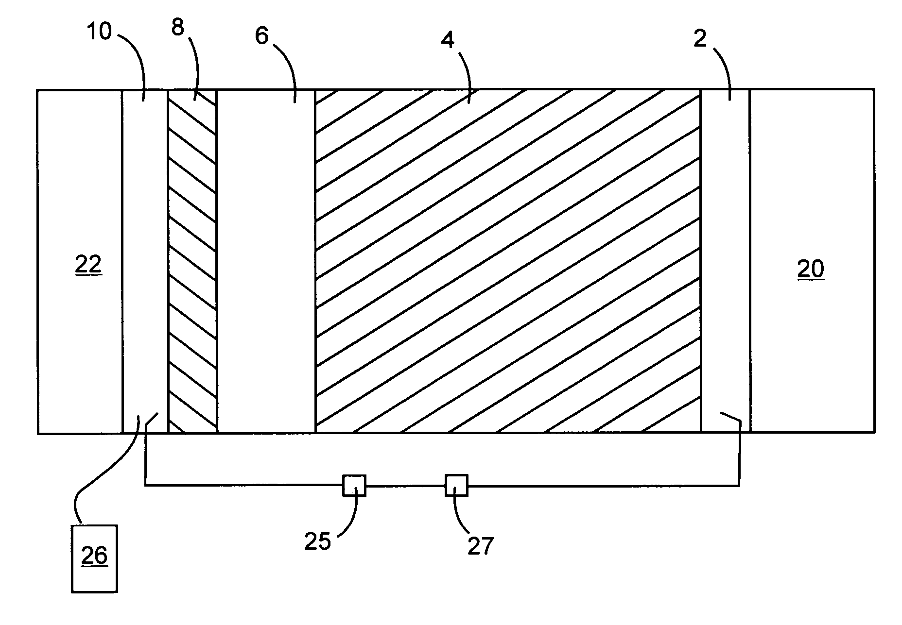
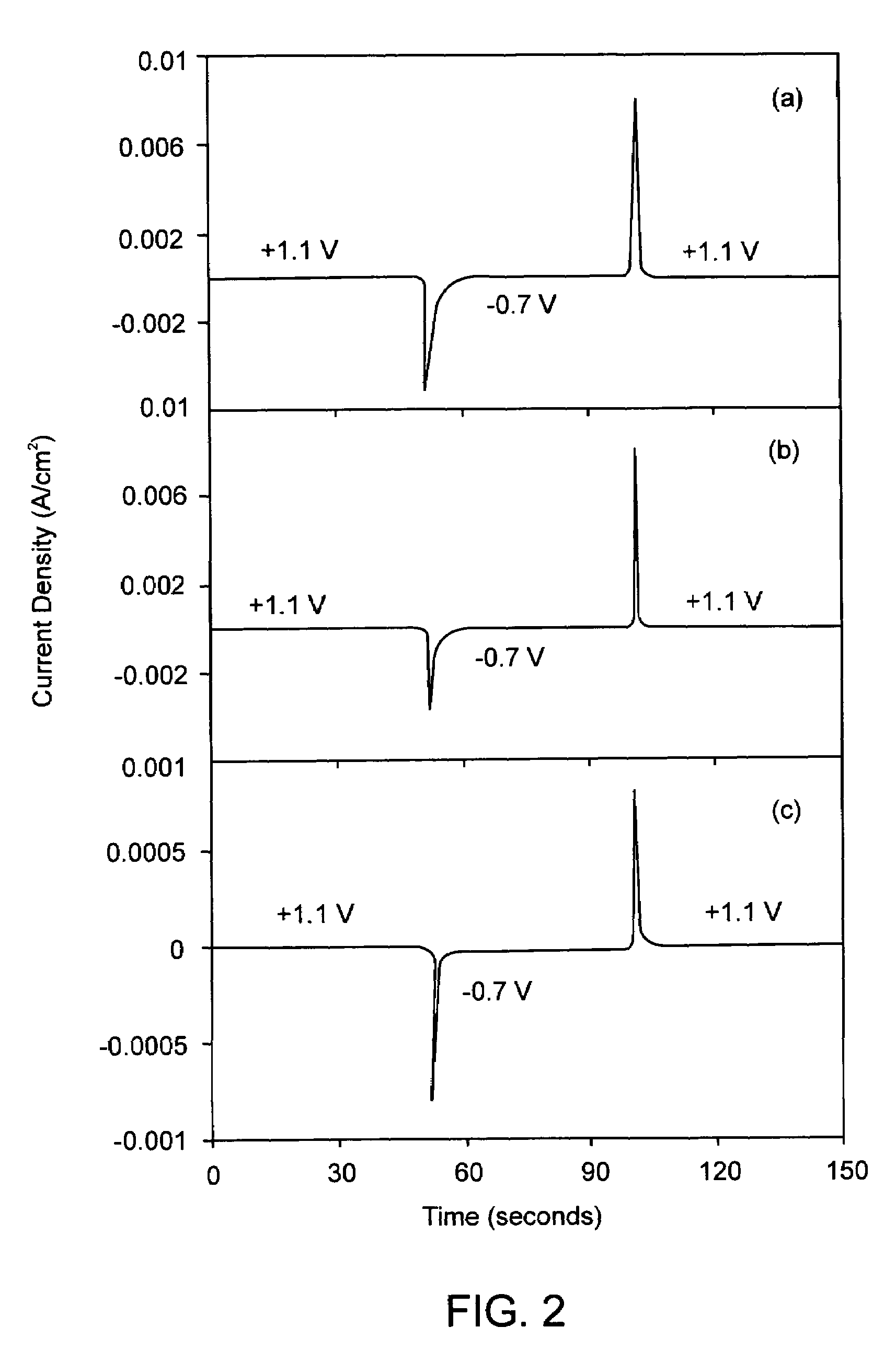
[0051]Electrochromic property tests were performed in an electrochemical-optical cell consisting of a Pt ring counter electrode and an Ag / AgCl reference electrode both sandwiched in between the coated ITO glass working electrode and a quartz window. The cell allows electrochemical measurements using a Gamry PC3 potentiostat and optical transmittance measurements using a fiber-optic-based spectrophotometer to be carried out simultaneously: H+ intercalation and deintercalation of W1−xTaxO3−x / 2 films were accomplished by varying the electrical potential of the films between −0.7 V (vs. Ag / AgCl) and +1.1 V (vs. Ag / AgCl) in 0.1 M H3PO4 electrolyte at a frequency of 0.01 Hz. Spectral transmittance of the film (plus a thin electrolyte layer of 6 mm thick and the quartz window of 3 mm thick) was measured in-situ using the spectrophotometer in the 250-850 nm ranges. The surface area of the films in contact with electrolyte is 4.1 cm2.

[0052]Ele...


PUM

PropertyMeasurementUnit
thicknessaaaaaaaaaa
thicknessaaaaaaaaaa
thickaaaaaaaaaa

Abstract

An electrochromic material having improved durability and more pleasing color characteristics is composed of a single-phase compound of formula W1−xTaxO3−x / 2, x having a value in a range of from about 0.15 to about 0.5. Thin films of the electrochromic material can be manufactured by pulse laser deposition (PLD). Thin films of the electrochromic material are useful in the fabrication of electrochromic devices, such as “smart” windows, mirrors, information displays and variable emittance surfaces.

Description

FIELD OF THE INVENTION [0001]The present invention is related to electrochromic materials and devices utilizing electrochromic materials.BACKGROUND OF THE INVENTION [0002]An average household spends over 40 percent of its annual energy budget on heating and cooling costs. Office buildings now account for about one-third of all the energy used in the U.S., a quarter of which is lost through the inefficiency of standard windows to retain heat in the winter or deflect heat in the summer. ‘Smart’ window has the capability to be tuned or dimmed, to permit desired amount of light to pass through it. Therefore, it will allow more sunlight into the rooms during the winter and block most of it during the summer. As a result, ‘Smart’ windows that can significantly minimize the energy consumption of residence and office buildings are in great demand. It is estimated that $11 billion to $20 billion dollars a year savings in heating, lighting and air-conditioning costs can be realized if the “sm...

Claims


Application Information

Patent Timeline
Patent Type & Authority Patents(United States)
IPC IPC(8): G02F1/15G02F1/1524
CPCC09K9/00G02F1/1523G02F1/1524
Inventor YANG, DONGFANGXUE, LIJUE
Owner NAT RES COUNCIL OF CANADA
Why Eureka
Try Eureka