
Electrolytic capacitors with a polymeric outer layer and process for the production thereof

a technology of polymer outer layer and electrolytic capacitor, which is applied in the manufacture of electrolytic capacitors, casings/cabinets/drawers, electrical equipment, etc., can solve the problems of high mechanical stress that may greatly increase the residual current of capacitor anodes, difficult formation of thick polymeric outer layers by in situ polymerisation, and large number of coating cycles. , to achieve the effect of improving the residual current of capacitors, simple and reliably reproducible, and good edge coverag

Active Publication Date: 2008-08-12
HERAEUS PRECIOUS METALS GMBH & CO KG
View PDF23 Cites 97 Cited by
  • Summary
  • Abstract
  • Description
  • Claims
  • Application Information

AI Technical Summary

Benefits of technology

"The present invention relates to a process for the production of solid electrolytic capacitors with low equivalent series resistance (ESR) and good edge coverage. The invention involves applying a dispersion containing particles of a conductive polymer, such as polyaniline or polythiophene, with a diameter of less than 700 nm, a binder, and solid particles having a diameter in the range from 0.7 μm to 20 μm to a capacitor body. The particles of the conductive polymer improve the formation of outer layers on electrolytic capacitors and smooth unevenness caused by the solid particles. The resulting capacitors have low unevenness and low residual current. The invention also provides a process for forming an electrically conductive polymeric outer layer by using a dispersion containing particles of a conductive polymer, a binder, and solid particles having a diameter in the range from 0.7 μm to 20 μm."

Problems solved by technology

High mechanical stresses that may greatly increase the residual current of the capacitor anode occur in particular during the production process when encapsulating the capacitor anodes.
The formation of a thick polymeric outer layer by in situ polymerisation is very difficult.
Layer formation requires a very large number of coating cycles in this process.
As a result of the large number of coating cycles, the outer layer is coated very unevenly, in particular the edges of the capacitor anode are often inadequately covered.
Japanese patent application JP-A 2003-188052 recites that homogeneous edge coverage requires expensive matching of the processing parameters.
However, this makes the production process very susceptible to interruptions.
An addition of binder materials for quicker layer build-up is also difficult, as the binder materials hinder the oxidative in situ polymerisation.
This contacting is very expensive in mass production and may damage the oxide layer.
However, high contact resistance between the individual powder particles results in excessive electrical resistance, preventing the production of solid electrolytic capacitors with low ESR.
A drawback of this method, however, is that the polymeric outer layer becomes very uneven (unevenness: 10 to 50 μm).
Voltage peaks and electrical breakdowns may also occur at the uneven points of the polymeric outer layer.
However, this process has the drawback that the PEDT / PSS complex does not penetrate into porous anode bodies with small pores.
Consequently, modern, highly porous anode materials cannot be used.
However, the drawback of these capacitors is that they have a high ESR of 130 mΩ and higher.
Although this process allows the edge coverage to be improved, it does not allow the production of polymeric outer layers having a reliably reproducible density.

Method used


Image

  • Electrolytic capacitors with a polymeric outer layer and process for the production thereof
  • Electrolytic capacitors with a polymeric outer layer and process for the production thereof
  • Electrolytic capacitors with a polymeric outer layer and process for the production thereof

Examples


example 1

Preparation of a Dispersion According to the Invention

[0256]Preparation of Conductive Particles b)

[0257]868 g deionised water, 330 g of an aqueous polystyrene sulphuric acid solution having an average molecular weight of 70,000 and a solids content of 3.8% by weight were placed in a 2-l three-necked flask with stirrer and internal thermometer. The reaction temperature was maintained between 20 and 25° C.

[0258]5.1 g 3,4-ethylenedioxythiophene were added while stirring. The solution was stirred for 30 minutes. 0.03 g iron(III) sulphate and 9.5 g sodium persulphate were then added and the solution was stirred for a further 24 hours.

[0259]Once the reaction has been completed, 100 ml of a strongly acid cation exchanger and 250 ml of a weakly basic anion exchanger were added, for removing inorganic salts, and the solution was stirred for a further two hours. The ion exchanger was filtered out.

[0260]The resulting poly(3,4-ethylenedioxythiophene) / polystyrene sulphonate dispersion had a soli...

example 2

Production of Capacitors

[0267]Production of Oxidised Capacitors

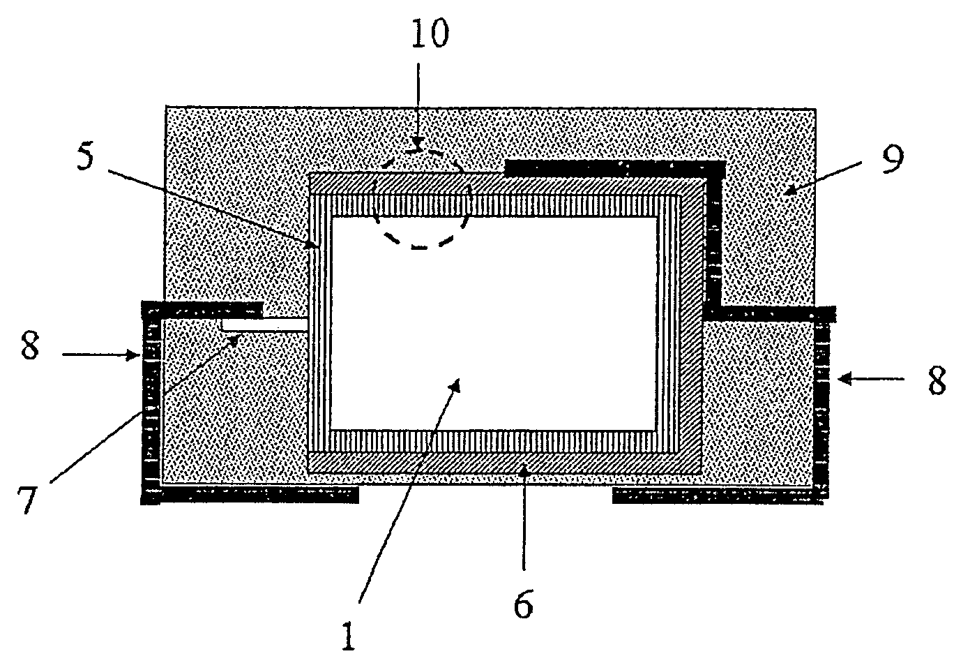
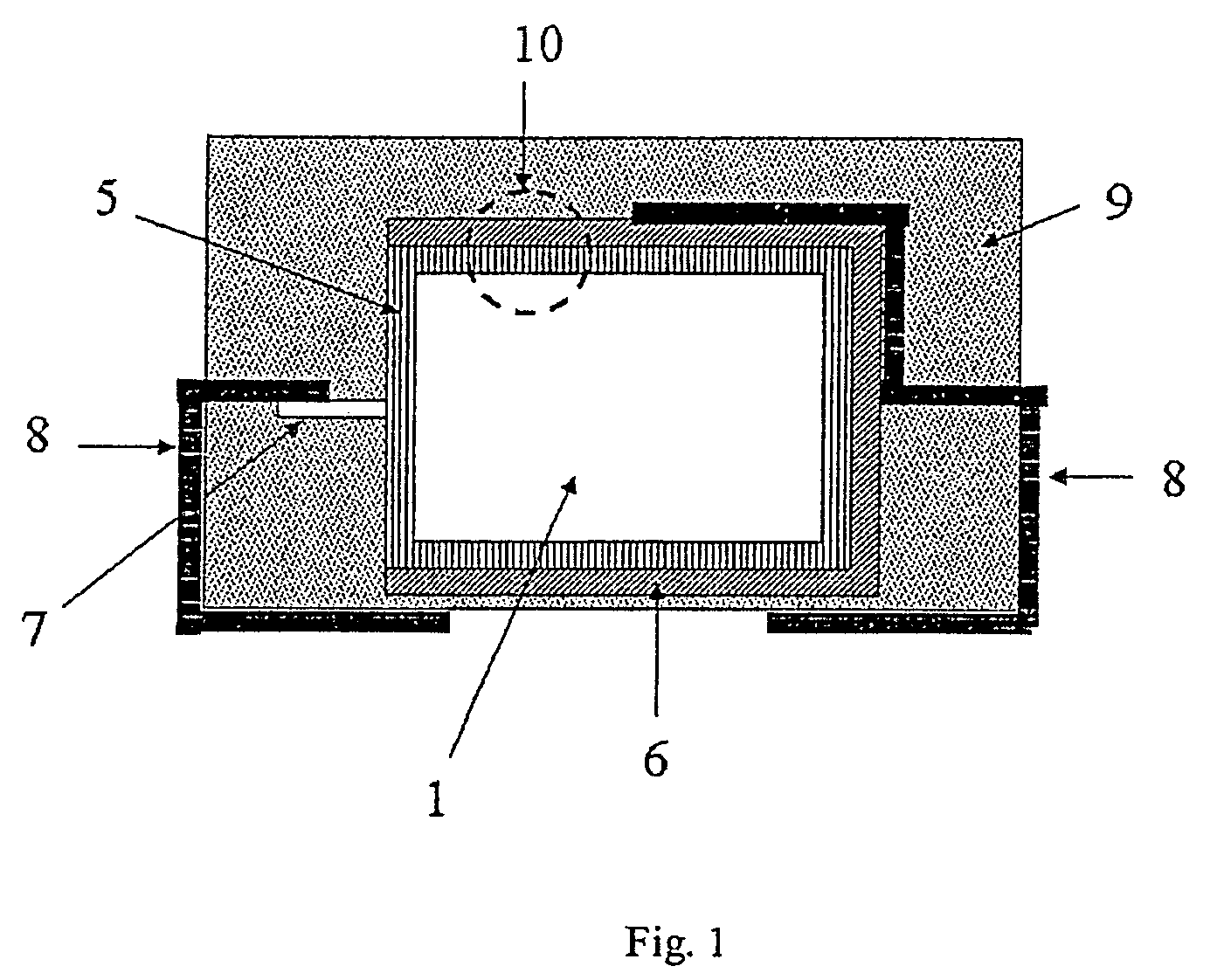
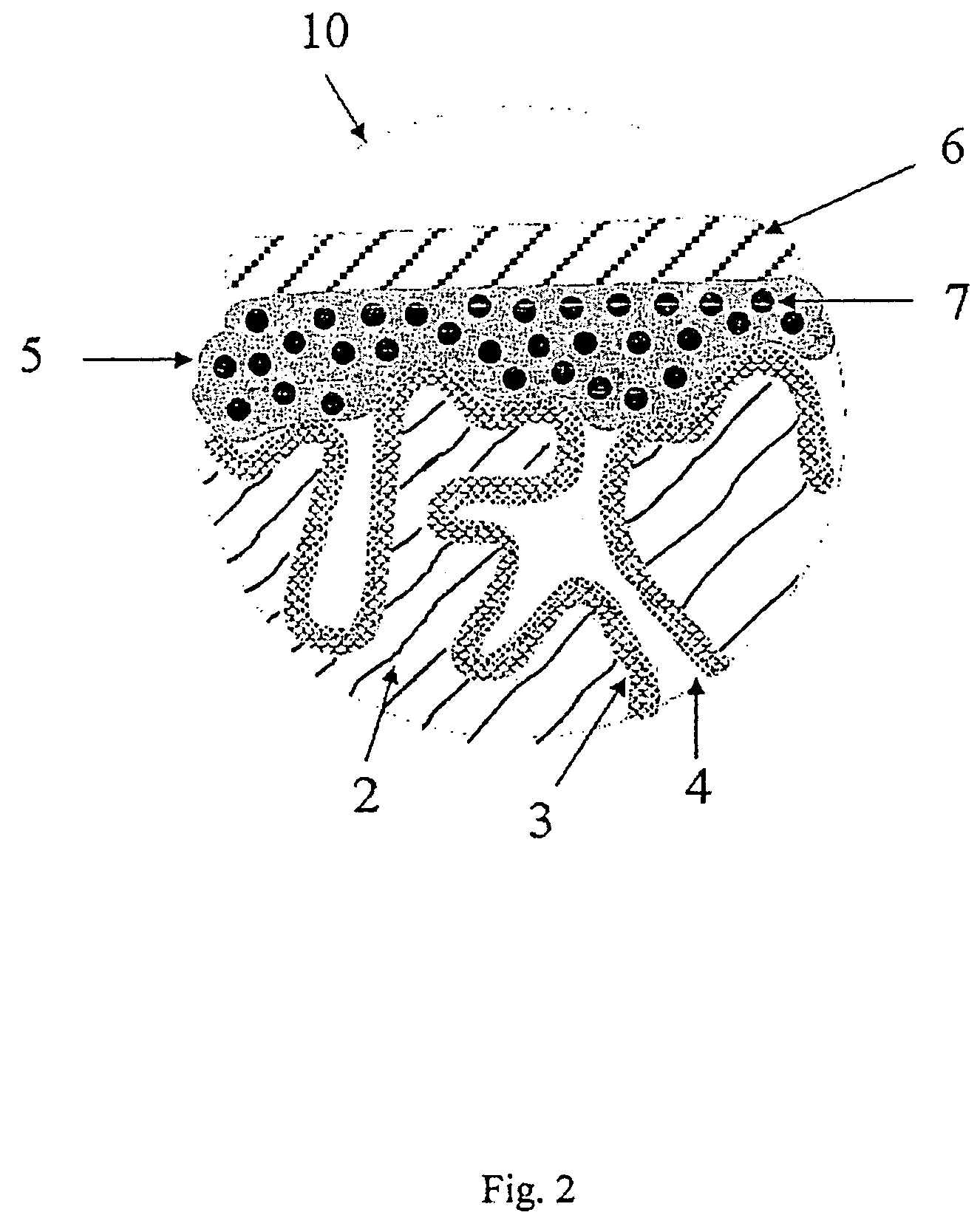
[0268]Tantalum powder with a specific capacitance of 50,000 μFV / g was compacted into pellets, a tantalum wire 7 being included, and sintered to form a porous electrode body 2 with dimensions of 4.2 mm*3 mm*1.6 mm. The electrode bodies 2 were anodised in a phosphoric acid electrolyte to 30 V.

[0269]Chemical In Situ Coating of the Electrode Bodies

[0270]A solution composed of 1 part by weight 3,4-ethylenedioxythiophene (BAYTRON® M, H. C. Starck GmbH) and 20 parts by weight of a 40% by weight ethanolic solution of iron(III)-p-toluenesulphonate (BAYTRON® C-E, H. C. Starck GmbH) was produced.

[0271]The solution was used to impregnate nine anodised electrode bodies 2. The electrode bodies 2 were steeped in this solution and then dried for 30 min at ambient temperature (20° C.). They were then heat treated for 30 min at 50° C. in a drying oven. The electrode bodies were then washed for 30 min in a 2% by weight aqueous solution of ...

example 3

Preparation of a Dispersion According to the Invention

[0286]In a beaker with stirrer, 180 g PEDT / PSS dispersion prepared according to Example 1.1, 10 g of a sulphopolyester (Eastek 1100, Eastman), 8 g dimethyl sulphoxide, 1 g 3-glycidoxypropyltrimethoxysilane (Silquest A-187, OSi Specialities) and 0.4 g of wetting agent (Dynol 604, Air Products) were mixed intensively for one hour. 2 g PEDT / toluene sulphonate powder (prepared according to Example 1.2) were then dispersed using a bead mill dissolver unit. For this purpose, 300 g of zirconium oxide beads (Ø 1 mm) were added and the mixture was stirred at 7000 rpm for one hour, while being cooled with water. Finally, the ground beads were separated via a 0.8-μm sieve. The dispersion had a solids content of 4.7%.

[0287]The distribution of the solid particles in the dispersion was determined by laser diffraction (MS 2000 Hydro S). The following diameter distribution values were obtained:

[0288]d10: 1.5 μm

[0289]d50: 3.0 μm (average diameter...


PUM

PropertyMeasurementUnit
diameteraaaaaaaaaa
diameteraaaaaaaaaa
diameteraaaaaaaaaa

Abstract

The invention relates to a process for the production of electrolytic capacitors with low equivalent series resistance and low residual current consisting of a solid electrolyte made of conductive polymers and an outer layer containing conductive polymers, to electrolytic capacitors produced by this process and to the use of such electrolytic capacitors.

Description

RELATED APPLICATIONS[0001]This application claims benefit to German application no. 10 2005 033 839 filed Jul. 20, 2005 which is incorporated by reference in its entirety for all useful purposes.BACKGROUND OF THE INVENTION[0002]1. Field of Invention[0003]The invention relates to a process for the production of electrolytic capacitors with low equivalent series resistance and low residual current consisting of a solid electrolyte made of conductive polymers and an outer layer containing conductive polymers, to electrolytic capacitors produced by this process and to the use of such electrolytic capacitors.[0004]2. Description of Related Art[0005]A conventional commercial solid electrolytic capacitor generally consists of a porous metal electrode, an oxide layer located on the metal surface, an electrically conductive solid introduced into the porous structure, an outer electrode (contacting), such as a silver layer, and further electric contacts and encapsulation.[0006]Examples of sol...

Claims


Application Information

Patent Timeline
Patent Type & Authority Patents(United States)
IPC IPC(8): H01G9/00H01G9/028H01G9/04H01G9/14
CPCH01G9/0036H01G9/028H01G9/042H01G9/15H01G11/56H01G11/48Y10T29/41Y02E60/13Y10T29/417H01G9/00H01G9/28
Inventor MERKER, UDOWUSSOW, KLAUS
Owner HERAEUS PRECIOUS METALS GMBH & CO KG
Learn More