Systems and methods for electrosurgical treatment of turbinates

Inactive Publication Date: 2008-10-28
ARTHROCARE
View PDF459 Cites 346 Cited by
  • Summary
  • Abstract
  • Description
  • Claims
  • Application Information

AI Technical Summary

Benefits of technology

[0022]In another embodiment, an electrosurgical instrument, such as a probe or catheter, comprises a shaft with proximal and distal ends, one or more electrode terminal(s) at the distal end and one or more connectors coupling the electrode terminal(s) to a source of high frequency electrical energy. In this embodiment, the electrode terminal(s) are preferably designed for cutting tissue; i.e., they typically have a distal edge or point. Conventional electrosurgery cuts through tissue by rapidly heating the tis

Problems solved by technology

When the sinus opening becomes blocked, the cavities fill, producing deep pain and pressure.
Enlarged turbinates cause the air space through the nasal passages to become restricted.
These measures, however, have limited effectiveness, and the long term use of such nasal sprays typically makes the problem worse.
Moreover, pharmaceuticals, particularly decongestant pills may cause high blood pressure, increase the heart rate and, for some people, cause sleeplessness.
While microdebriders have been promising, these devices suffer from a number of disadvantages.
For one thing, the tissue in the nasal and sinus cavities is extremely vascular, and the microdebrider severs blood vessels within this tissue, usually causing profuse bleeding that obstructs the surgeon's view of the target site, Controlling this bleeding can be difficult since the vacuuming action tends to promote hemorrhaging from blood vessels disrupted during the procedure.
In addition, the microdebrider often must be removed from the nose periodically to cauterize severed blood vessels, which lengthens the procedure.
Moreover, the serrated edges and other fine crevices of the microdebrider can easily become clogged with debris, which requires the surgeon to remove and clean the microdebrider during the surgery, further increasing the length of the procedure.
More serious concerns, however, are that the microdebrider is not precise, and it is often difficult, during the procedure, to differentiate between the target sinus tissue, and other structure

Method used


Image

  • Systems and methods for electrosurgical treatment of turbinates
  • Systems and methods for electrosurgical treatment of turbinates
  • Systems and methods for electrosurgical treatment of turbinates

Examples


Embodiment Construction

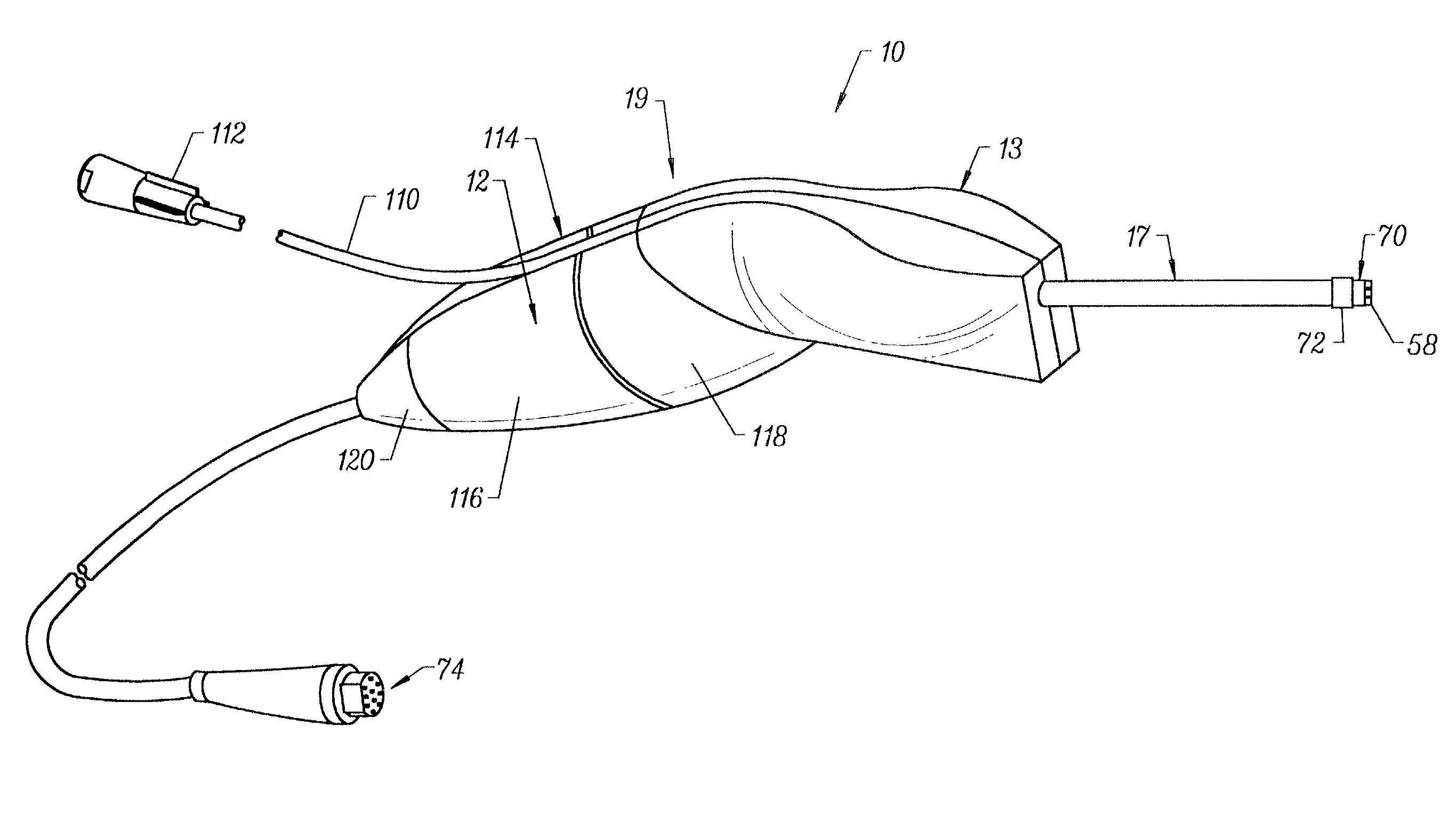
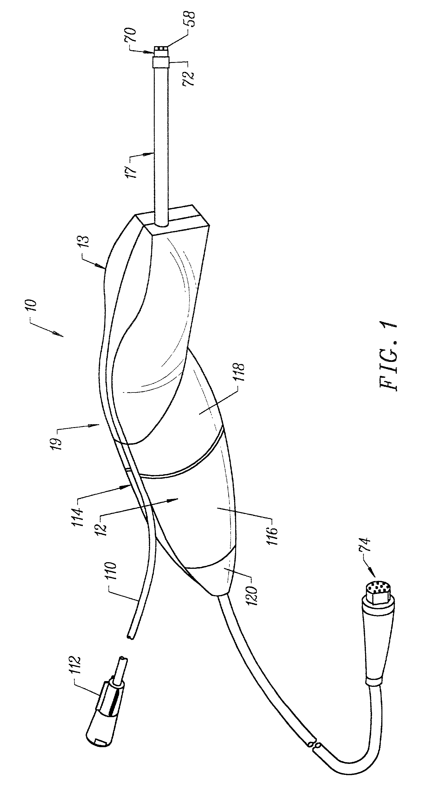
[0040]The present invention provides systems and methods for selectively applying electrical energy to a target location within or on a patient's body, particularly including tissue in head and neck, such as the ear, mouth, pharynx, larynx, esophagus, nasal cavity and sinuses. These procedures may be performed through the mouth or nose using speculae or gags, or using endoscopic techniques. These procedures may include the removal of swollen tissue, chronically-diseased inflamed and hypertrophic mucus linings, polyps and / or neoplasms from the various anatomical sinuses of the skull, the turbinates and nasal passages, in the tonsil, adenoid, epi-glottic and supra-glottic regions, and salivary glands, submucus resection of the nasal septum, excision of diseased tissue and the like. In other procedures, the present invention may be useful for collagen shrinkage, ablation and / or hemostasis in procedures for treating snoring and obstructive sleep apnea (e.g., soft palate, such as the uvu...


PUM

PropertyMeasurementUnit
Lengthaaaaaaaaaa
Angleaaaaaaaaaa
Angleaaaaaaaaaa

Abstract

The present invention provides systems and methods for selectively applying electrical energy to a target location within the head and neck of a patient's body, particularly including tissue in the ear, nose and throat. In one aspect, a method is provided for reducing the volume of enlarge swollen tissue in the patient's nose, such as swollen nasal tissue, mucus membranes, turbinates, polyps, neoplasms, cartilage (e.g., the nasal septum) or the like. In particular, the turbinates are treated by positioning one or more electrode terminal(s) adjacent to the turbinates, and delivering electrically conductive fluid, such as isotonic saline, to the nasal cavity to substantially surround the electrode terminal(s) with the fluid. High frequency voltage is applied between the electrode terminal(s) and one or more return electrode(s) to remove a small tissue segment, channel or hole from the region near or in the turbinates to shrink the turbinates and prevent swelling, due to the formation of scar tissue as the wound heals. The high frequency voltage may be selected to effect a small amount of thermal damage to the walls of the channel or hole to facilitate the formation of scar tissue without extending this thermal damage beyond the immediate region of the target site.

Description

RELATED APPLICATIONS[0001]The present application is a division of U.S. patent application Ser. No. 09 / 480,880 filed Jan. 10, 2000, now U.S. Pat. No. 6,659,106, which is a continuation of U.S. patent application Ser. No. 09 / 054,323 filed Apr. 2, 1998, now U.S. Pat. No. 6,063,079, which is a continuation-in-part of U.S. patent application Ser. No. 08 / 990,374, filed Dec. 15, 1997, now U.S. Pat. No. 6,109,268, which is a continuation-in-part of U.S. patent application Ser. No. 08 / 485,219, filed on Jun. 7, 1995, now U.S. Pat. No. 5,697,281, the complete disclosures of which are incorporated herein by reference for all purposes.[0002]The present invention is related to commonly assigned co-pending Provisional Patent Application No. 60 / 075,059, filed on Feb. 18, 1998, U.S. patent application Ser. No. 09 / 010,382, filed Jan. 21, 1998, and U.S. patent application entitled “Systems and Methods for Selective Electrosurgical Treatment of Body Structures”, filed Feb. 27, 1998, U.S. patent applic...

Claims


Application Information

Patent Timeline
IPC IPC(8): A61B18/14A61B17/00A61B18/00A61B18/12A61F2/02A61M1/00A61M3/02
CPCA61B18/1206A61B18/1402A61B18/148A61B18/1482A61B18/1485A61B18/149A61B18/1492A61B18/042A61B2017/00026A61B2017/00084A61B2017/00101A61B2017/00247A61B2018/00029A61B2018/00083A61B2018/00119A61B2018/0016A61B2018/00178A61B2018/00327A61B2018/00392A61B2018/00505A61B2018/00577A61B2018/00583A61B2018/00601A61B2018/00666A61B2018/00678A61B2018/00702A61B2018/0072A61B2018/00726A61B2018/00779A61B2018/00791A61B2018/00827A61B2018/00875A61B2018/00982A61B2018/1213A61B2018/124A61B2018/1253A61B2018/126A61B2018/1273A61B2018/1407A61B2018/1467A61B2018/1472A61B2018/162A61B2018/165A61B2218/002A61B2218/007A61F2/2493A61M3/0283
Inventor HOVDA, DAVID C.THAPLIYAL, HIRA V.EGGERS, PHILIP E.ELLSBERRY, MARIA B.
Owner ARTHROCARE
Why Eureka
Try Eureka