Metallurgical reactor for the production of cast iron

Inactive Publication Date: 2008-11-25
SMS DEMAG SPA
View PDF13 Cites 7 Cited by
  • Summary
  • Abstract
  • Description
  • Claims
  • Application Information

AI Technical Summary

Benefits of technology

[0009]In accordance with a further characteristic feature of the present invention, in order to overcome this problem, cooling elements are arranged in the wall section situated opposite the slag bath and the slag bath/cast iron transition zone, said elements being intended to remove the heat from the bath with an intensity such as to cause solidification of the slag and therefore prevent erosion of the refractory material, to a depth of penetration of said erosion, known as “freeze line”, of acceptable magnitude, namely sufficient for ensuring the structural stability of the remaining wall.
[0010]Advantageously, these cooling elements consist of plates made of metal with a high thermal conductivity, for example copper, formed preferably from a laminate in order to take advantage of the optimum mechanical properties and the improved thermal conductivity, compared to copper produced by means of casting,

Problems solved by technology

One of the main problems in these reactors is that of ensuring both the regular descent of the charge material into the underlying slag bath and the elimination or reduction to a minimum of the material lost as a result of entrainment by the gases flowing out from the reactor.
This, combined with the chemical aggress

Method used


Image

  • Metallurgical reactor for the production of cast iron
  • Metallurgical reactor for the production of cast iron
  • Metallurgical reactor for the production of cast iron

Examples


Embodiment Construction

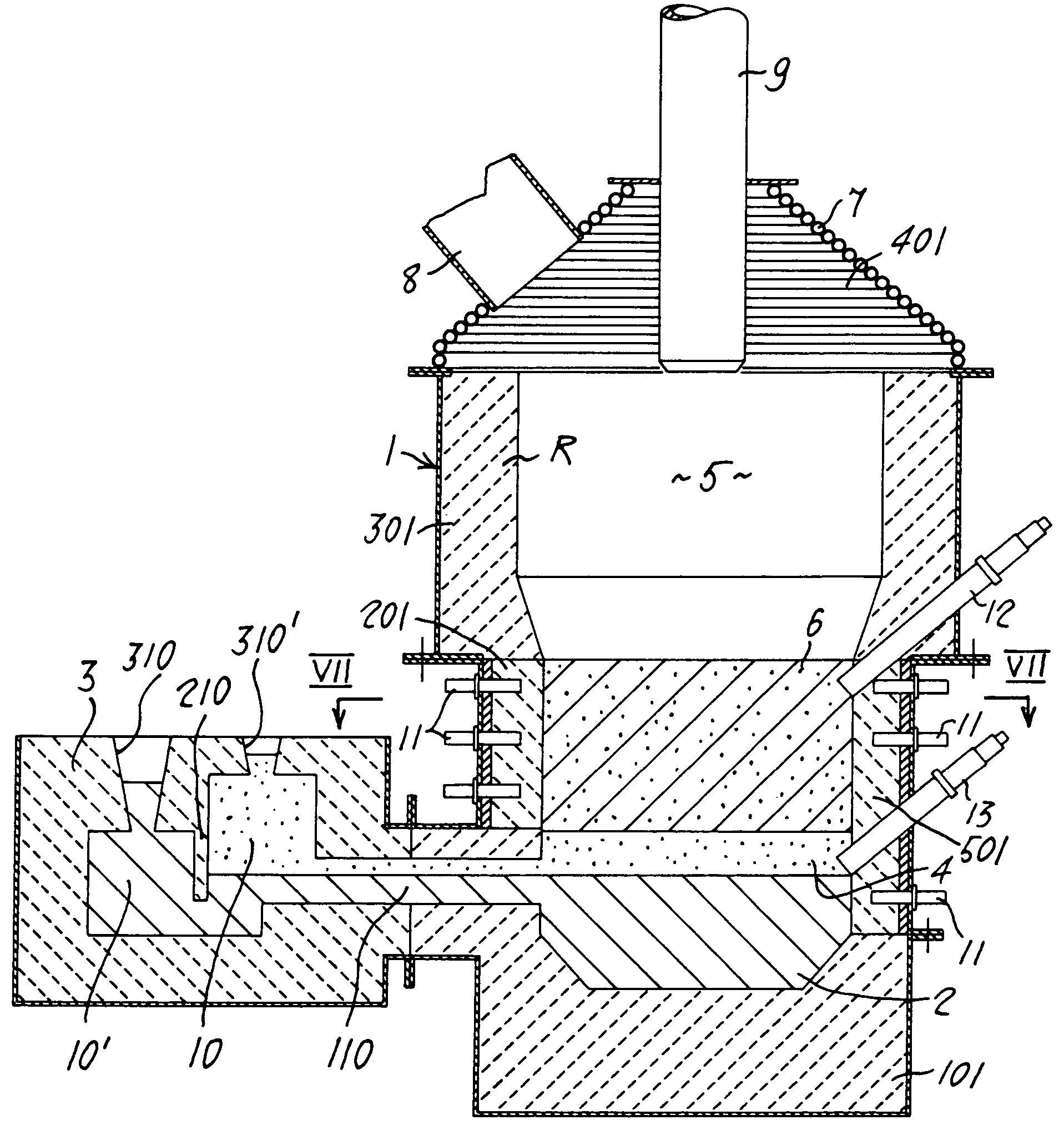
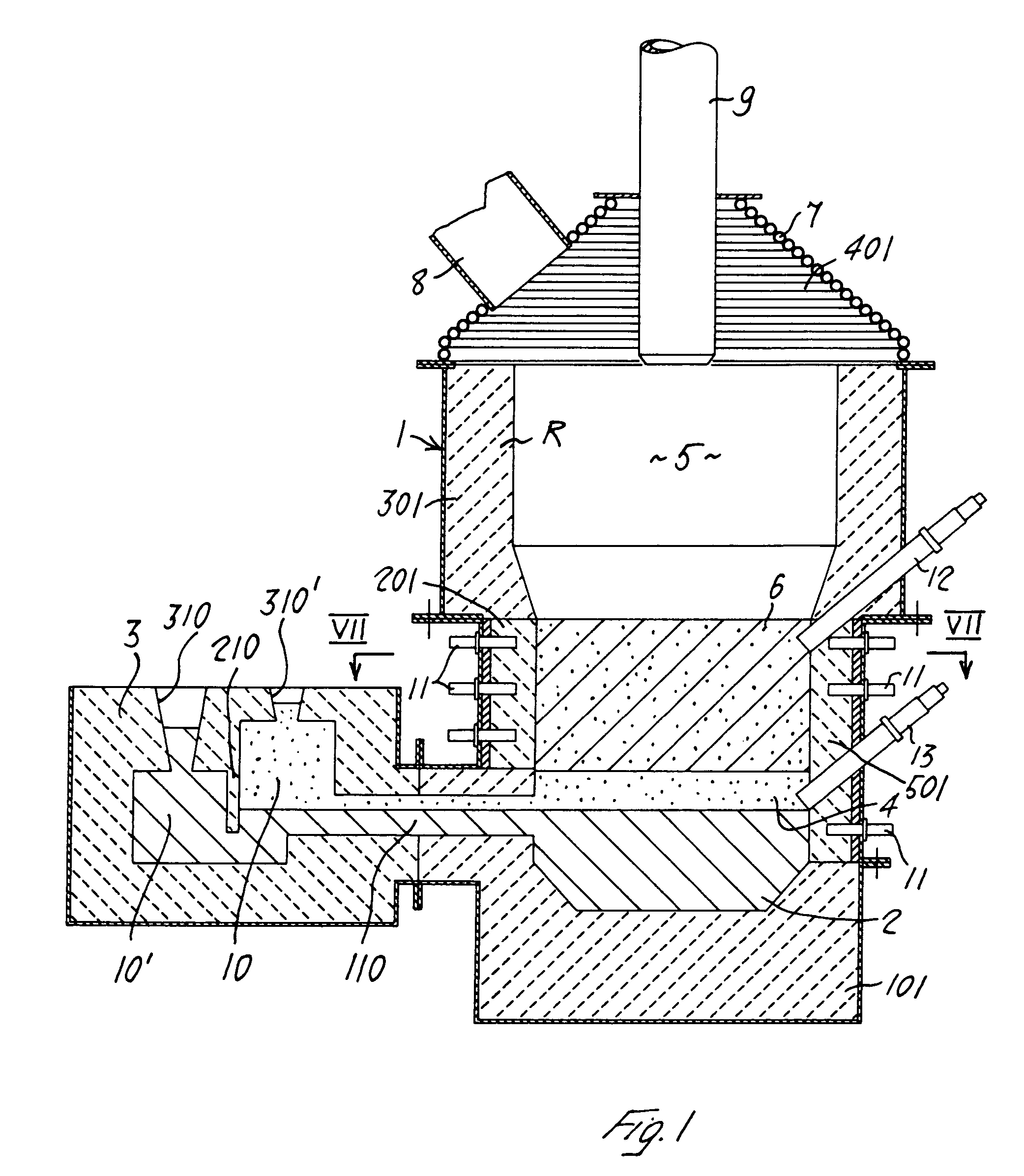
[0020]With reference to the accompanying figures and in particular to FIG. 1 thereof, 1 denotes the metal casing of the reactor, having an approximately cylindrical shape. This casing 1 is lined internally at least partially with a refractory material R suitable for containing the reacting materials. In the reactor shown it is possible to distinguish three zones containing liquid with a density decreasing from the bottom upwards, namely the liquid cast iron bath 2 contained in the crucible 101, the transition zone 4 for the cast iron 2 and the actual slag 6, both contained inside an approximately cylindrical casing. The reactor wall has, formed therein, level with said transition layer 4 a hole 110 communicating with an external “calming” well 3 which allows settling of the two phases 2 and 4 and separation from each other as a result of overflow, by means of a suitable diaphragm210 consisting of two different sections 10, 10′ of the said well, for extraction said phases from the re...


PUM

PropertyMeasurementUnit
Heightaaaaaaaaaa

Abstract

Metallurgical reactor for the production of cast iron, consisting of a metal casing internally lined, at least partially, with refractory material and provided, in the region of the top closure, with a duct through which high-temperature ferrous material is introduced, said reactor being equipped with a first series of lances for injecting the comburent gas, which are suitably directed and arranged on at least a first bottom level situated in the vicinity of the crucible for collecting the cast iron and through which, in association with a comburent gas, coal of suitable grain size is blown by means of a suitable carrier gas. Said duct has suitable cooling means and is provided, in the bottom terminal part, with nozzles for blowing in compressed gas. The middle zone of the casing of the reactor is lined internally with refractory material, pockets for receiving plates made of metal which is a good heat conductor being formed in said lining, said plates being provided on their side directed towards the outside of the reactor with heat exchanger means for cooling thereof.

Description

BACKGROUND AND SUMMARY OF THE INVENTION[0001]The present invention relates to metallurgical reactors, and more particularly so-called “smelter” metallurgical reactors suitably for carrying out a cast iron production process forming part of the group of processes known as “smelting reduction” processes. According to this group of processes, the cast iron is produced from: a material containing iron, for example iron ore and / or other reducible metal oxides such as manganese, nickel, chromium, etc., where applicable pre-heated and / or pre-reduced; a carbon-based reducing material, for example coal; a comburent gas containing oxygen, for example industrial oxygen. The products of the process are: liquid cast iron composed of an alloy of iron and other metals with a high concentration of carbon in solution form; the liquid slag, mainly composed of calcium, silicon, magnesium and aluminium oxides, and a gas containing sizeable fractions of carbon monoxide and carbon dioxide resulting from ...

Claims


Application Information

Patent Timeline
IPC IPC(8): C21B13/04C21B11/02C21B13/00C21C1/00C21C1/08F27B1/16F27B1/20F27B1/24F27D3/15F27D3/16
CPCC21B11/02C21B13/0026C21C1/08F27B1/16F27B1/20F27B1/24F27D3/1554F27D3/16
Inventor FONTANA, PIERGIORGIODE MARCHI, GIOVANNIMOLINARI, ALESSANDRO
Owner SMS DEMAG SPA
Why Eureka
Try Eureka