CO2 removal from gas using ionic liquid absorbents

a technology of ionic liquid absorbent and gas, which is applied in the direction of gaseous fuels, hydrogen sulfides, separation processes, etc., can solve the problems of large operating expense, high energy requirement, and large capital expense of diluted concentration, and achieve low hydrocarbon solubility, low co-absorption, and high co2 capacity

Inactive Publication Date: 2009-05-05
CHEVROU USA INC
View PDF2 Cites 32 Cited by
  • Summary
  • Abstract
  • Description
  • Claims
  • Application Information

AI Technical Summary

Benefits of technology

[0025]Among other factors the present invention provides a new process for removing CO2 from hydrocarbon containing gas streams using an ionic liquid absorbent. The new process and method has a unique mix of properties that provide advantages over prior processes. The process of the present invention has a high CO2 capacity, low hydrocarbon solubility (low co-absorption), and requires low energy for regeneration of the ionic liquid absorbent. The unique set of desirable features of the present invention makes it economically advantageous over current commercial physical and chemical absorption systems.

Problems solved by technology
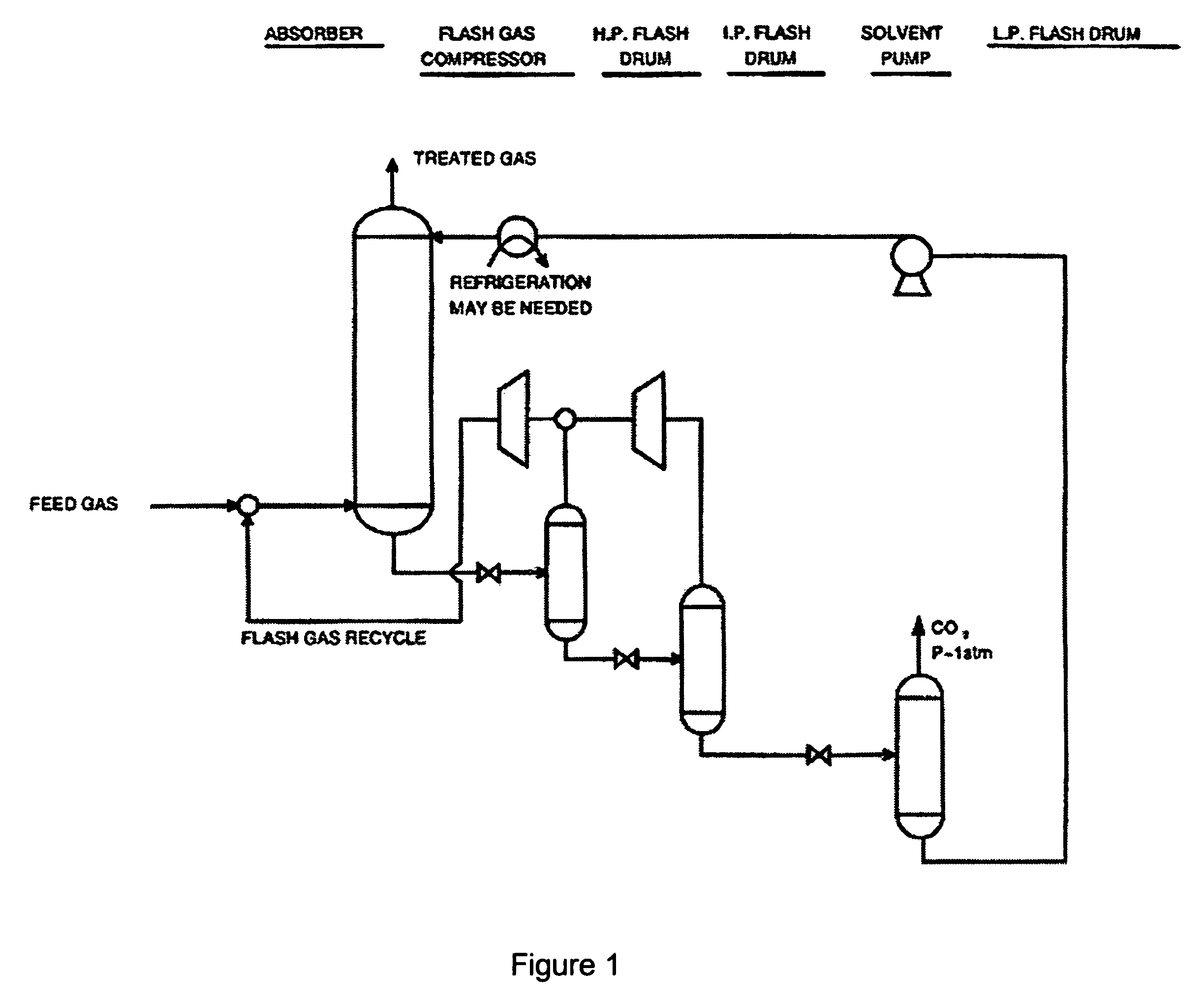
Also, CO2 in the presence of water can be a corrosive agent to metal pipes.
Although an effective CO2 separation process, amine treating presents several issues and challenges:1. Intensive energy requirements: During the regeneration step, heating energy is required to break the chemical bonds between the absorbed CO2 and solvent.
For some particularly strongly-absorbing amines (e.g., MEA) and for large circulation rates, this energy requirement can be very high and represents a significant operating expense.
However, this diluted concentration requires higher circulation rates to achieve the desired CO2 removal.
High circulation rates require larger process equipment (capital expense), increased reboiler duty (energy / operating expense) and increased pumping costs (energy / operating expense).
Inhibitors are also typically used to control corrosion, but are often toxic.3. CO2 loading capacity: CO2 loading capacity is limited by the concentration (or diluteness) of the amine solution.
Also, the regenerated amine solution, although lean in CO2, still contains some absorbed CO2—reducing its capacity and reducing the driving force in the absorber.
This is due to increased corrosion potential effecting the longevity of the equipment.
Even if corrosion inhibitors are used, serious viscosity problems can occur when using high concentrations of amines which can lead to hydraulic failures.4. Degradation of amine: Amines react with CO2 (and H2S, COS, etc.) to form various different products that are not reversible in the regeneration step.
Amines may also degrade thermally.
This ‘reclaimer’ step generates waste products and requires additional energy.
Because of the significant costs involved, proper amine selection requires careful evaluation of these factors for the specific application since the criticality of these factors varies for different amines.
Nevertheless, in general, the main disadvantage for amine-based CO2 removal processes remains the high energy consumption requirements.
However, physical absorption processes also have several disadvantages:1. Low CO2 capacity: Physical solvents tend to have lower CO2 capacities than amine solvents.
Thus, higher circulation rates and larger equipment is needed.
Higher circulation rates result in higher capital and operating expenses.
Also, absorber columns using physical solvents typically have more stages of contact and are therefore much taller than those employing amine solutions.4. Solvent losses: Physical solvents can be entrained and lost to the treated gas.
Refrigeration or water-washing may be used to minimize losses but this requires added capital expense and increased operating cost.

Method used


Image

  • CO2 removal from gas using ionic liquid absorbents
  • CO2 removal from gas using ionic liquid absorbents
  • CO2 removal from gas using ionic liquid absorbents

Examples


example 1

Experimental Methods

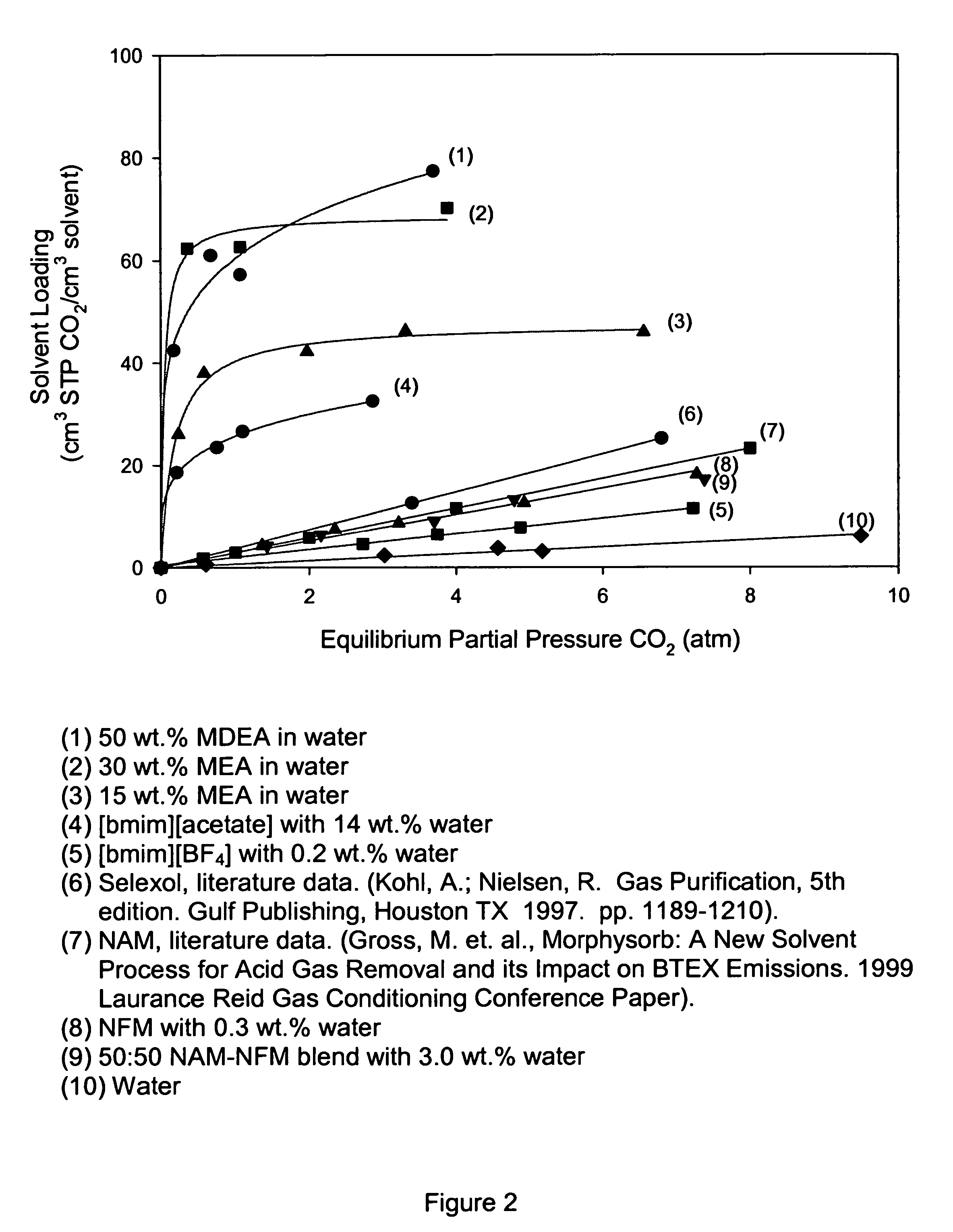
[0062]This example shows the procedures used for generating loading curves shown in FIG. 2. All of the ionic liquids ([bmim][acetate], [bmim][BF4]) and physical solvents (e.g., NAM, NFM) were used as-received. The water content for each solvent, as determined by Karl-Fischer titration, is summarized below:

[0063]

[bmim][acetate]:14.0wt. %H2O[bmim][BF4]:0.21wt. %H2ONAM:0.15wt. %H2ONFM:0.28wt. %H2O

[0064]The aqueous amine solvents were prepared by diluting the pure amine with the appropriate amount of water. The amine concentrations were chosen to match those that are commonly used in the gas processing and refining industries (50 wt. % MDEA, 30 wt. % MEA, etc.).

[0065]Gas sorption measurements were conducted with a static, volumetric method. A known mass (2 to 4 grams) of solvent was added to a clean, pressure vessel of known volume (˜25 cm3). The sample vessels are all equipped with a relief valve, inlet sampling plug valve, and a digital pressure gauge. After zeroin...

example 2

CO2 Loading Curves in Solvents

[0066]Gas loadings (cm3 STP / cm3 liquid) were calculated using the ideal gas law from the initial and equilibrium gas pressures, temperature, solvent volume, and vessel volume. The presence of air and water vapor in the gas phase must be accounted for when applying this method, especially for the high-temperature data.

[0067]FIG. 2 shows the room-temperature, pure CO2 loading curves for several solvents. CO2 loadings are reported on a volumetric basis (cm3 STP CO2 / cm3 solvent) to account for any differences in densities between the solvents. Several clear trends can be seen in the data.

[0068]The aqueous amines (1-3) all had the highest volumetric CO2 loadings over the entire pressure range, and have curves that rise steeply initially and then plateaus at higher pressures. This is characteristic of chemical absorption (“chemisorption”), which is expected because it is well-known that amine groups can reversibly bind CO2 either as a carbamate species (with ...

example 3

CO2 Loading Curves in “Hybrid” Ionic Liquids

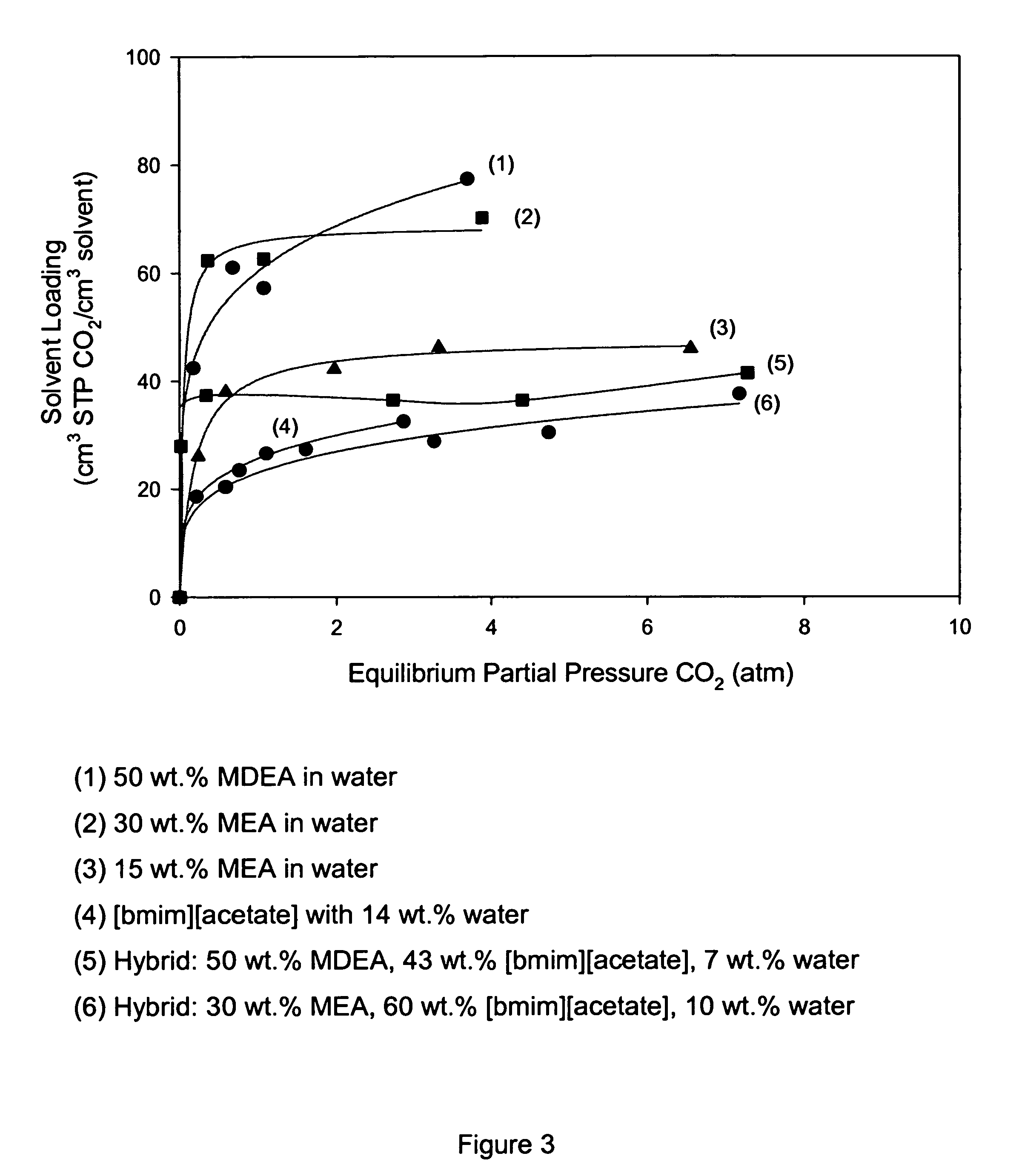
[0071]Experiments were performed to investigate the effect of blending pure amines with [bmim][acetate]. FIG. 3 shows the room-temperature CO2 loading curves for the aqueous amines (1-3), [bmim][acetate] (4), and two different amine blends of [bmim][acetate] (5-6). The MDEA-[bmim][acetate] blend behaved similar to that of pure [bmim][acetate]. This is consistent with the notion that both MDEA and [bmim][acetate] bind CO2, in the presence of water, as a bicarbonate species. However, when the amine was changed from MDEA to MEA, we see that the blend has the highest observed CO2 loading curve among all ionic liquids. With MEA, CO2 is able to bind directly as a carbamate species at a 2:1 ratio of MEA:CO2. At higher partial pressures, CO2 can also bind as bicarbonate species under the influence of the [acetate] functionality. Because of these different mechanisms, the MEA-[bmim][acetate] loading curve has a peculiar shape. The aqueous amines (1...


PUM

PropertyMeasurementUnit
weight %aaaaaaaaaa
weight %aaaaaaaaaa
temperaturesaaaaaaaaaa

Abstract

A process and method for separating CO2 from a gaseous stream such as natural gas. An ionic liquid comprising an anion having a carboxylate function and an effective amount of water is used as an adsorbent to selectively complex the CO2 yielding a gaseous stream with a greatly reduced CO2 content. The ionic liquid can then be readily be regenerated and recycled.

Description

CROSS REFERENCE TO RELATED APPLICATIONS[0001]This application is a Continuation-in-Part of U.S. patent application Ser. No. 10 / 737,090 filed Dec. 16, 2003 which is incorporated by reference herein in its entirety.BACKGROUND OF THE INVENTION[0002]Carbon dioxide (CO2) is an undesired diluent that is present in many natural gas and other gas sources. The removal of CO2 is a common separation process in natural gas processing and is often required to improve the fuel quality (heating value) of the natural gas. Also, CO2 in the presence of water can be a corrosive agent to metal pipes. As a consequence, the removal of CO2 to acceptable specifications is required prior to transport natural gas or in pipelines. In the natural gas processing industry, various technologies have been employed for CO2 removal including chemical solvents, physical solvents, and membranes. By far, chemical solvents that reversibly react with CO2 are most commonly used for CO2 removal. Commonly used chemical solv...

Claims


Application Information

Patent Timeline
Patent Type & Authority Patents(United States)
IPC IPC(8): B01D53/14
CPCB01D53/1475B01D53/1493Y02C10/06Y02C10/08B01D53/04B01D53/14C10L3/104B01D2252/2041B01D2252/30B01D2252/504B01D2257/504B01D2258/0283Y02C20/40
Inventor CHINN, DANIELVU, DE Q.DRIVER, MICHAEL S.BOUDREAU, LAURA C.
Owner CHEVROU USA INC
Why Eureka
Try Eureka