High-CO high-conversion-rate isothermal shift reactor

A technology of isothermal conversion and reactor, which is applied in chemical instruments and methods, bulk chemical production, inorganic chemistry, etc., can solve the problems of easy aging of reaction catalysts, high conversion rate requirements, and large thermal stress of pipelines, etc., to achieve high conversion High efficiency, simple process, and the effect of less cooling water

Active Publication Date: 2015-04-08
HUNAN ANCHUN ADVANCED TECH
View PDF6 Cites 2 Cited by
  • Summary
  • Abstract
  • Description
  • Claims
  • Application Information

AI Technical Summary

Problems solved by technology

[0024] 1. Coal gas containing 68.65% CO, the shift gas is used for ammonia or hydrogen production, and the conversion rate of the shift gas CO is reduced to ~0.4%, which requires a high conversion rate. More than 99% requires four stages and five shift furnaces, and the shift reactor is too large There are many, there is an air-gas heat exchanger, 6 cooling condensers, and a water spray cooler; at least 17 main equipment are required, so there are too many equipment and too many connecting pipes; the floor area is large, the investment is large, and the operation High difficulty;
[0025] 2. If the CO in the untransformed gas is as high as 70% to 86%, there are more equipment and longer connecting pipes, the transformation cannot be realized even with four to five stages of adiabatic transformation;
[0026] 3. 85% of the total amount of CO is reacted at 380°C to 430°C. The high temperature makes the reaction catalyst easy to age and affects the service life. The high-temperature reaction equipment pipes are subject to high thermal stress and high material requirements;
[0027] 4. The temperature of most catalysts reaches 400°C, high temperature reaction is not conducive to chemical equilibrium, and more catalysts are needed to achieve the same conversion rate;
[0028] 5. The heat of reaction steam condensation is used to generate low-pressure (such as 0.6MPa ~ 2.5MPa) steam, and there is still a large amount of condensed water to be discharged, so the utilization rate is low;

Method used


Image

  • High-CO high-conversion-rate isothermal shift reactor
  • High-CO high-conversion-rate isothermal shift reactor
  • High-CO high-conversion-rate isothermal shift reactor

Examples


Embodiment 1

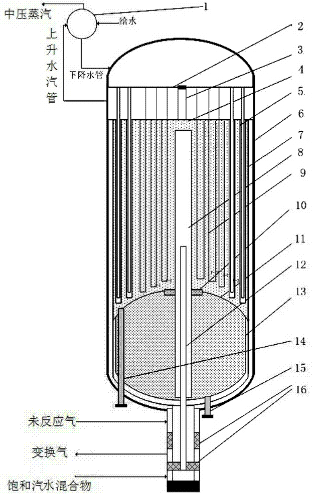
[0077] The CO in the unreacted gas of the present invention can be as high as 85% or more, and the CO in the shifted gas can be reduced to 0.4%. The shift reactor catalyst is a sulfur-resistant cobalt-molybdenum catalyst composed of MOS and COS. The temperature of the catalyst bed in the present invention is within the low-end range of the active temperature (230°C- 310°C), the maximum temperature difference between the axial and radial directions of the reaction bed is only within 3°C to 8°C.

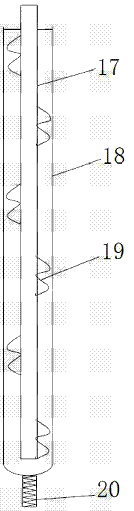
[0078] The isothermal shift reactor 5 is cylindrical as a whole, such as image 3 As shown, by upper tube plate 2, charging tube 3, lower tube plate 4, double sets of water vapor pipes 5, shell 6, upper radial catalytic bed 7, center pipe 8, U-shaped water vapor pipe 9, annular communicating hole 10, The support head 11, the steam-water mixture nozzle 12, the lower radial catalytic bed 13, the upper discharge pipe 14, the lower discharge pipe 15, the sealing packing 16, the bottom tee...

Embodiment 2

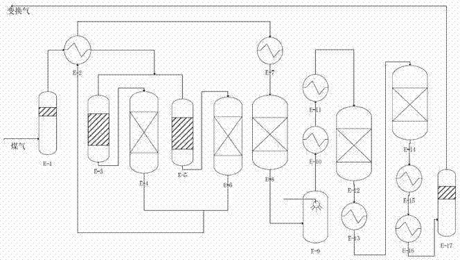
[0090] Such as Figure 4 As shown, the CO volume concentration matched with the isothermal shift reactor of the present invention is 40% to 70%, and the gas shift process flow of water-gas ratio is 1.3 to 1.6, which consists of the first water separator E-41, the heat exchanger E -42, purification and detoxification devices E-43, E-44, isothermal shift reactor E-45, first waste heat boiler E-46, second waste heat boiler E-47, second water separator E-48, Boiler feed water heater E-49, water cooler E-410, third water separator E-411. During operation, the coal containing CO passes through the first water separator E-41 and enters the heat exchanger E-42. The unreacted gas is heated to 230°C-240°C and enters the purification and detoxification devices E-43, E-44, Chlorine, phosphorus, oxygen, and hydrocarbons in the gas are removed here, and a small amount of CO is also converted. After the gas temperature rises to 255 ° C ~ 265 ° C, it enters the isothermal shift reactor E-45,...

Embodiment 3

[0093] Such as Figure 5 As shown, the CO 50%-85% industrial furnace gas (such as acetylene furnace gas, steelmaking converter, yellow phosphorus furnace gas) conversion process flow matched with the isothermal shift reactor of the present invention.

[0094] Industrial furnace gas is characterized by high C0% content (40% to 85%), basically no water vapor, basically no sulfur, but high dust content, high oxygen content, and acetylene furnace gas also contains unsaturated hydrocarbons.

[0095] Such as Figure 5 As shown, the isothermal transformation process is used to match the process by E-51 washing tower, E-52 water separator, parallel filters E-53, E-54, compressor E-55, oil remover E-516, purification and removal Poison E-56, E-57, Hydrogenation Converter E-517, Isothermal Shift Reactor E-58, Steam Dryer E-59, Heat Exchanger E-510, Boiler Desalination Water Heater E-511, Desalination Composed of oxygen water heater E-512, air cooler E-513, fifth water separator E-514,...


PUM


Abstract

An isothermal carbon monoxide (CO) shift reactor having high CO conversion and the process technology comprises the outside pressure vessel; the catalyst unit; tipper and lower tube sheets welded with water tubes and bottom tee joints; the said outside pressure vessel has seal heads at the upper and lower ends; the said vessel has a water chamber and a steam chamber at the upper section. The catalyst unit comprises the upper catalyst bed with water tubes. There is a central pipe that is located in the said vessel, of which the upper end is located in the upper catalyst bed while the lower end is located in the lower catalyst bed; the said bottom tee joint has an inlet for feed gas, outlet for reacted shift gas and inlet for steam-water mixture; the said central pipe is installed with spray nozzle for steam-water mixture; the said reactor is applicable for process technologies for feed and effluent gas having different CO contents. Low temperature, high CO feed content, high shift conversion and low system pressure drop are direct results of this disclosure.

Description

technical field [0001] The present invention relates to the fields of synthetic ammonia, methanol synthesis, ethylene glycol production, coal-to-oil, coal-to-natural gas, hydrogen production and utilization of industrial furnace waste gas, in particular to a high-CO high conversion rate reactor and process flow, involving industrial furnace tail gas, CO (up to 85% or more) in industrial gas reacts with water vapor to become hydrogen, realizing a shift reactor and process with high conversion rate (up to 98.5% or more). Background technique [0002] Coal gas, natural gas conversion gas, coke oven gas conversion gas, calcium carbide furnace tail gas, blast furnace gas, etc., all of these gases contain a large amount of CO. different methods), CO can be transformed into useful H 2 , the transformed reaction is: [0003] CO+H 2 O (steam) = CO 2 +H 2 +Q [0004] The conversion reaction is an exothermic reversible reaction, there must be a catalyst and an excess of H 2 O (w...

Claims


Application Information

Patent Timeline
Patent Type & Authority Patents(China)
IPC IPC(8): C01B3/16
CPCB01J8/0457B01J8/025B01J8/0278B01J8/0407B01J8/0415B01J8/0453B01J8/0473B01J8/0492B01J8/0496B01J2208/00123B01J2208/00132B01J2208/0053C01B3/14C01B3/16C01B2203/0283C01B2203/1205Y02P20/129Y02P20/52
Inventor 谢定中
Owner HUNAN ANCHUN ADVANCED TECH
Why Eureka
Try Eureka