
Laser irradiation method, laser irradiation apparatus and method for manufacturing semiconductor device

a laser irradiation and laser irradiation technology, applied in the direction of manufacturing tools, polycrystalline material growth, crystal growth process, etc., can solve the problems of extremely low absorption efficiency of semiconductor films, uneven crystal diameter or crystallinity, and inability to achieve uniform crystallinity, and increase the mobility of the crystal. , the effect of reducing the size of the crystal

Inactive Publication Date: 2009-09-08
SEMICON ENERGY LAB CO LTD
View PDF30 Cites 6 Cited by
  • Summary
  • Abstract
  • Description
  • Claims
  • Application Information

AI Technical Summary

Benefits of technology

The present invention provides a laser annealing method using a pulsed laser with a high repetition rate, such as a 10 MHz or higher, without the need for a non linear optical element. This method has advantages such as higher absorption efficiency of the semiconductor film and larger grain crystals, resulting in higher mobility and better performance of the semiconductor device. The use of a high repetition rate laser also increases productivity by enhancing the crystallization process. The method utilizes a fundamental wave emitted from a pulsed laser with a high repetition rate, which has a low absorption efficiency in the semiconductor film. The use of a high repetition rate laser allows for a higher intensity laser beam, which can be absorbed by a thinner semiconductor film, resulting in faster formation time and higher productivity. The method also utilizes multiphoton absorption to melt the semiconductor film, reducing the thickness of the film. Overall, this method provides a more efficient and effective method for laser annealing.

Problems solved by technology

A conventional laser annealing method using laser light oscillated from a pulsed excimer laser has some problems to be solved, for example, a problem that crystal diameter or crystallinity is not uniform, a problem that electric characteristics of a TFT are not stable, and the like.
However, in the case of using a CW laser and a quasi-CW laser using a solid state laser medium, the wavelength band of the fundamental wave is from red ray to near-infrared ray, and absorption efficiency of the semiconductor film is extremely low.

Method used


Image

  • Laser irradiation method, laser irradiation apparatus and method for manufacturing semiconductor device
  • Laser irradiation method, laser irradiation apparatus and method for manufacturing semiconductor device
  • Laser irradiation method, laser irradiation apparatus and method for manufacturing semiconductor device

Examples


embodiment mode 1

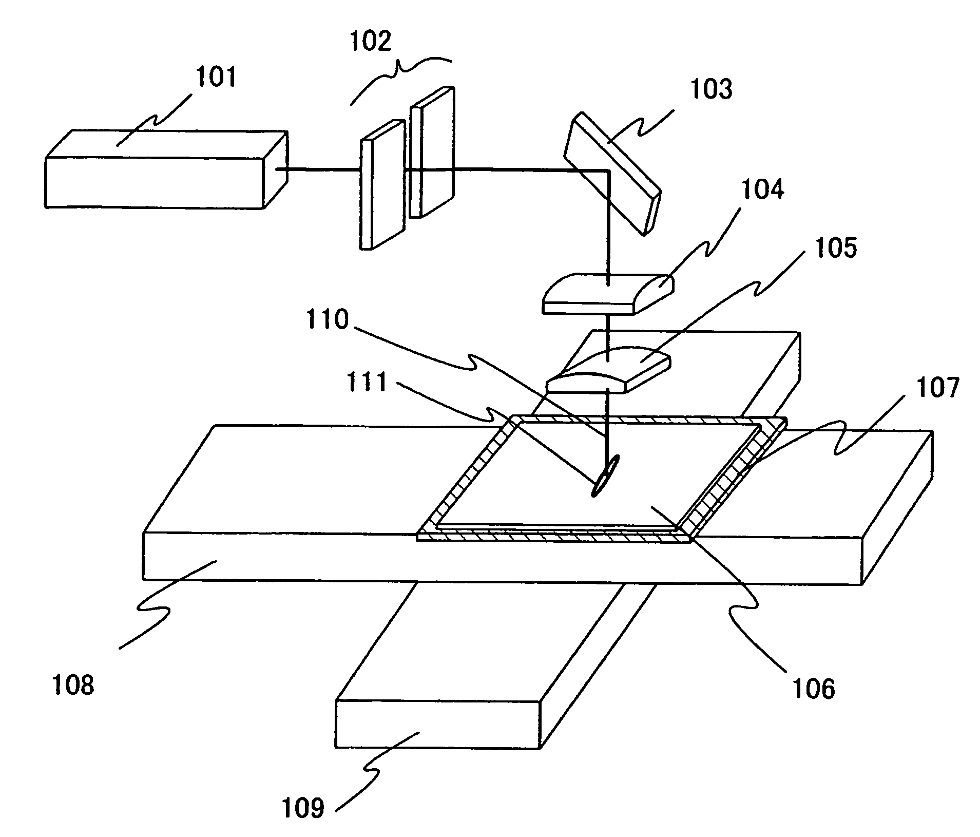
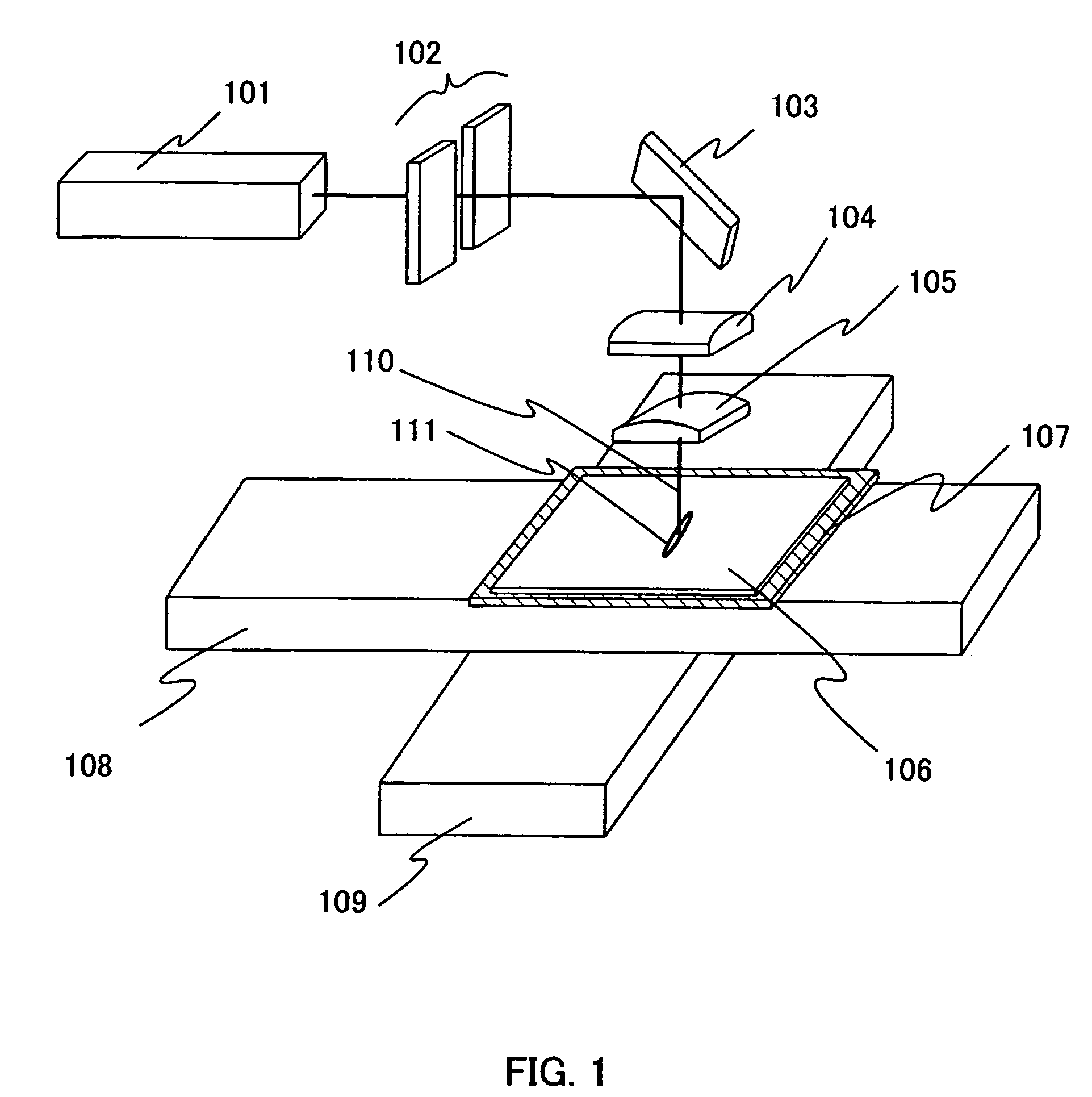
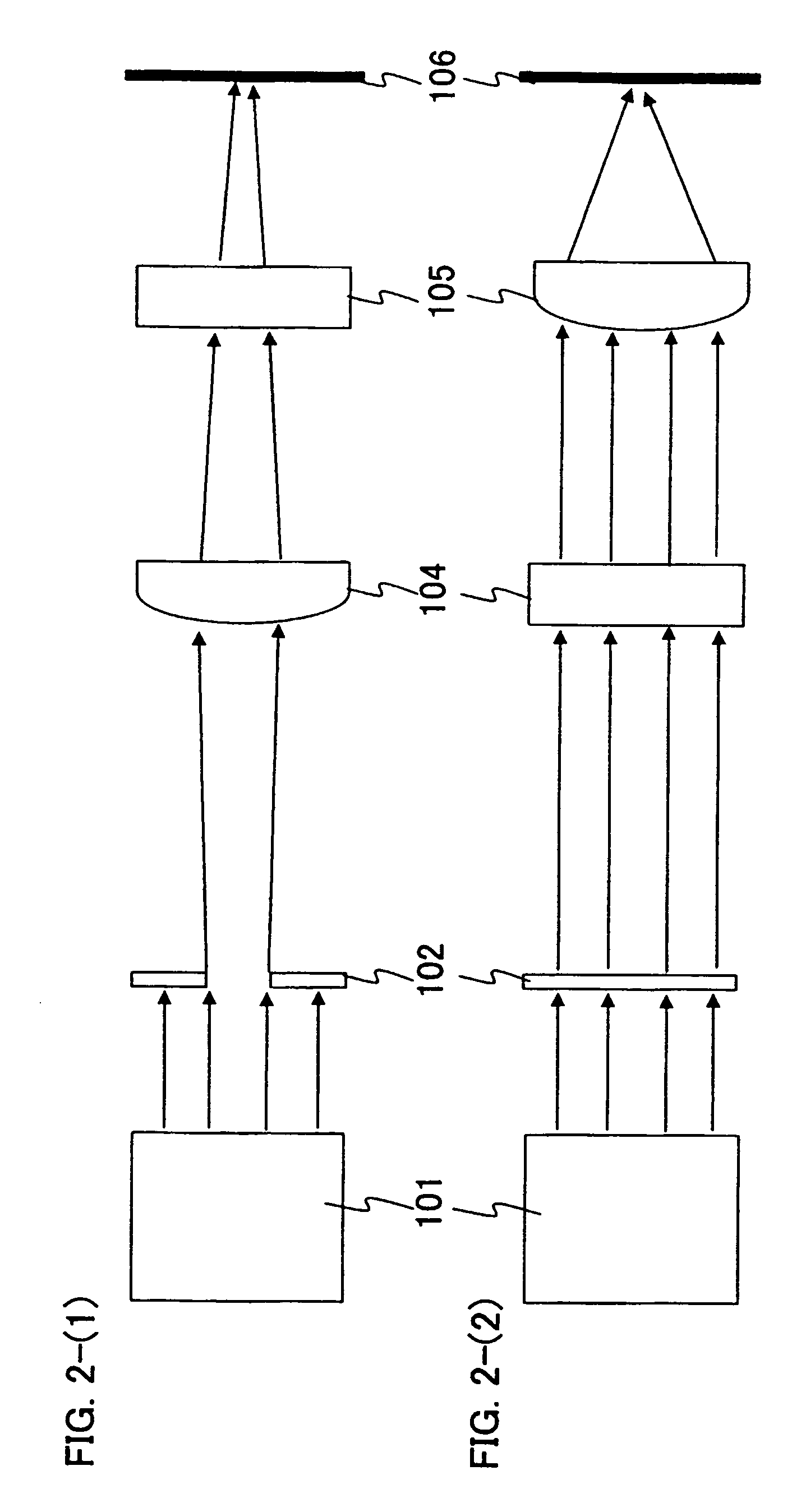
[0066]FIG. 1 shows one example of a laser irradiation apparatus according to the present invention.

[0067]As a laser oscillator 101 shown in FIG. 1, a laser oscillator that oscillates with a pulse width in the range of femtosecond (10−15second) is used (also referred to as a femtosecond laser). As the laser oscillator, lasers in which Nd, Yb, Cr, Ti, Ho, Er, and the like are added as a dopant into crystals of Sapphire, YAG, ceramics YAG, ceramics Y2O3, KGW, KYW, Mg2SiO4, YLF, YVO4, GdVO4 and the like are given. Note that a non linear optical element is not included in the laser oscillator 101 and thus a fundamental wave of a laser beam is emitted. A non linear optical element for converting light oscillated from a laser medium to a harmonic is not included in the pulsed laser oscillator 101; however, the pulsed laser oscillator 101 has high enough light intensity to generate a non linear optical effect (multiphoton absorption) in a semiconductor film.

[0068]A laser beam emitted from t...

embodiment mode 2

[0086]A manufacturing process of a top gate TFT according to the present invention is shown briefly with reference to FIGS. 5A to 5E. Laser light that has a repetition rate of 10 MHz or more and that is a fundamental wave is delivered to a semiconductor film having an amorphous structure (hereinafter, also referred to as an amorphous semiconductor film) and a non linear optical effect (multiphoton absorption) is caused to conduct crystallization.

[0087]As shown in FIG. 5A, a base insulating film 11 serving as a blocking layer and an amorphous semiconductor film 12 are formed over a substrate 10 having an insulating surface.

[0088]A glass substrate such as a barium borosilicate glass or an alumino borosilicate glass is used for the substrate 10 having an insulating surface. In addition, a plastic substrate that can endure a processing temperature in this process, for example, a plastic substrate obtained by processing, into a sheet-like form, a material in which inorganic particles wit...

embodiment mode 3

[0113]A dual gate TFT to which the present invention is applied is described below as an example with reference to FIG. 7.

[0114]In a TFT shown in FIG. 7, a base insulating film 711 is formed over a substrate 710 having an insulating surface and a lower electrode 712 is formed over the base insulating film 711.

[0115]The lower electrode 712 can be formed with a metal or a polycrystal semiconductor doped with one conductivity type impurity element. If a metal is used, tungsten (W), molybdenum (Mo), titanium (Ti), tantalum (Ta), aluminum (Al) and the like can be used. Here, tungsten is used for the lower electrode 712 and the tungsten layer is formed with a thickness of 50 nm. It should be noted that the thickness of the lower electrode 712 may be 20 to 50 nm.

[0116]After that, the lower electrode 712 is formed by etching the tungsten layer with the use of a mask (for example, a resist mask). For example, at this time, the resist mask can be narrowed by applying oxygen plasma. When the e...


PUM

PropertyMeasurementUnit
thicknessaaaaaaaaaa
temperatureaaaaaaaaaa
output poweraaaaaaaaaa

Abstract

In conducting laser annealing using a CW laser or a quasi-CW laser, productivity is not high as compared with an excimer laser and thus, it is necessary to further enhance productivity. According to the present invention, a fundamental wave is used without putting laser light into a non linear optical element, and laser annealing is conducted by irradiating a semiconductor thin film with pulsed laser light having a high repetition rate. A laser oscillator having a high output power can be used for laser annealing, since a non linear optical element is not used and thus light is not converted to a harmonic. Therefore, the width of a region having large grain crystals that is formed by scanning once can be increased, and thus the productivity can be enhanced dramatically.

Description

TECHNICAL FIELD[0001]The present invention relates to a laser irradiation apparatus for irradiating an object with laser light, a method for forming a crystalline semiconductor film using the apparatus, and a manufacturing method of a semiconductor device. In addition, the present invention relates to a semiconductor device having a circuit including a thin film transistor (also referred to as a TFT) or a photovoltaic device (such as an optical sensor or a solar battery). Further, the present invention relates to an electronic device incorporating, as a part thereof, e.g., an electro-optic device typified by a liquid crystal display panel, a light-emitting display device having an organic light-emitting element, a sensor device such as a line sensor, or a memory device such as SRAM.[0002]Note that a semiconductor device in this specification means a generic device which can operate with use of semi-conductive characteristics and includes all types of devices such as an electro-optic...

Claims


Application Information

Patent Timeline
Patent Type & Authority Patents(United States)
IPC IPC(8): H01L21/00C30B13/00
CPCB23K26/0736B23K26/0738B23K26/0853H01L21/2026H01L21/268H01L27/1266H01L27/1285H01L27/1296H01L27/1255Y10T117/1076H01L29/78621H01L29/78648H01L21/02683H01L21/02686H01L21/02422H01L21/02532
Inventor TANAKA, KOICHIROYAMAMOTO, YOSHIAKI
Owner SEMICON ENERGY LAB CO LTD
Learn More