Erosion and corrosion resistant protective coating for turbomachinery methods of making the same and applications thereof

a technology of corrosion resistance and protective coating, which is applied in the direction of machines/engines, mechanical equipment, superimposed coating process, etc., can solve the problems of debonding and delamination of the composite skin of the blade, wear, delamination of the rotor blade components of the helicopter, etc., to achieve high flexibility, high erosion and corrosion resistance properties, and high reflectivity of sun radiation

Active Publication Date: 2016-11-01
UNITED STATES OF AMERICA THE AS REPRESENTED BY THE SEC OF THE ARMY +1
View PDF23 Cites 16 Cited by
  • Summary
  • Abstract
  • Description
  • Claims
  • Application Information

AI Technical Summary

Benefits of technology

[0013]A hard wearing ceramic surface provides high flexibility when the coating thickness exceeds 20 μm yet, has high erosion and corrosion resistance properties and high reflectivity of the sun's radiation. The coating is multilayers, or alternating metal layers and ceramic layers. Sublayer thickness and coarseness vary among the layers across the multiple layers so the coating remains flexible against the thin metal substrate that is a sheath for protecting turbomachinery yet presents a tough outer surface that is resistant to erosion and corrosion.

Problems solved by technology

The rotorblades of modern helicopters are made of composite materials and suffer from wear due to sand and rain erosion as well as overheating by absorbing the sun's infrared rays.
Wear degrades the adhesive used in these laminated composites and results in debonding and delaminating the blade's composite skin.
Specifically, the high temperatures resulting from the blade absorbing the sun's infrared rays cause bonding deterioration and delamination of helicopter rotor blade components.
In addition to the ultraviolet effects of the sun, erosion, poor repairs and repeated high cyclical loading exasperates the problems of wear causing minute openings in the rotorblade's skin.
This invention, while helping to protect the rotor blade against overheating, does not help in preventing deterioration due to sand and rain erosion.
While this invention improves the bonding between the abrasion strip and the blade, it does not help to substantially improve the erosion resistance of the strip which will result in the necessity of replacing the strip too often especially when helicopters operate in harsh environments.
The vapor deposition of Schroeder is conducted at relatively low temperature, thus the substrate will have lost little of its initial high strength properties, however, the requirement of low surface roughness of the deposited layer is not addressed by U.S. Pat. No. 5,152,774.
Unfortunately these coatings are too thin for application as a protective erosion and corrosion resistive coatings for protective shields of the helicopter rotor blades.
In addition these coatings do not have high enough reflectivity to reduce the heat ingested from the sun's radiation.
Any post-deposition heat treatment which may be required to maintain corrosion resistance of the substrate, may lead to internal stresses in the coating due to differences in the grain size, and can eventually lead to abrasion, spalling, crack formation, grain separation, surface fractures, uneven edges and rough surfaces, and the like, which can drastically reduce the wear resistance and durability of coated objects.
None of the above discussed methods are concerned with even grain size and surface structure, and low micro-roughness of the vapor deposited hard, ceramic coatings.
Another disadvantage of the above mentioned conventional PVD and CVD technologies is that they are producing the hard, but brittle coatings which have very limited ductility, unable for bending without developing a large cracks, fracturing and delaminations.
This makes these coatings non-applicable for such applications as protective shields for the helicopter rotor blades made of thin metal sheets or foils.
The disadvantage of this type of coating is its limited thickness range, which makes it non-applicable as erosion and corrosion resistive coatings for the protective shields of helicopter rotor blades.

Method used


Image

  • Erosion and corrosion resistant protective coating for turbomachinery methods of making the same and applications thereof
  • Erosion and corrosion resistant protective coating for turbomachinery methods of making the same and applications thereof
  • Erosion and corrosion resistant protective coating for turbomachinery methods of making the same and applications thereof

Examples


example 1

Large Area Filtered Arc Deposition of Erosion and Corrosion Resistant TiAlN Multilayer Multi-Segment Coating on Metal Sheets, Foils, Instruments and Machine Components

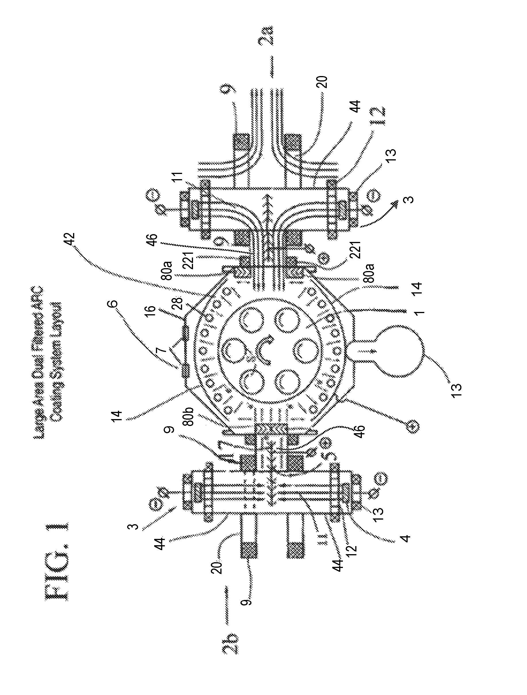
[0064]The arc coating apparatus shown in FIG. 1 is used in this process. The apparatus is equipped with two dual-filtered arc sources, 2a and 2b having round cathodes 4 measuring 3″ in diameter and 2″ in height, one filtered arc source 2a having titanium targets and the other 2b having aluminum targets. The exit openings of the filtered arc sources are equipped with load lock shutters 80a, 80b, electron-permeable to provide a free passage of electron current from the cathode targets 4 to distal auxiliary anodes 14 to thereby establish an auxiliary arc discharge.

[0065]A 12″ wide×60″ long× 1 / 64″ thick stainless steel metal strip as a substrate 8 is installed around the turntable 1 with the center of the strip positioned at an even height with the center of the opening of the plasma duct 46. The metal strip substrate is s...

example 2

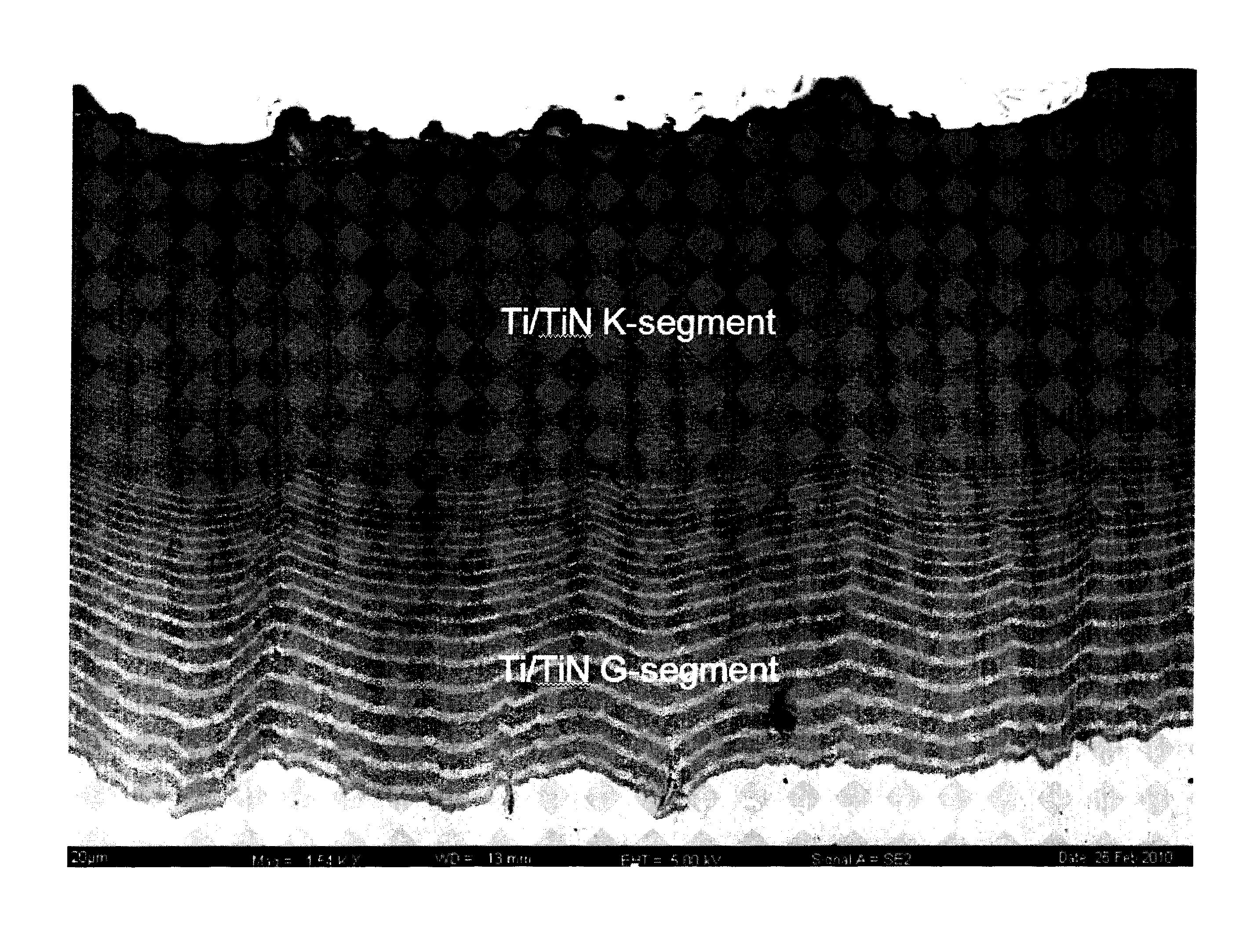
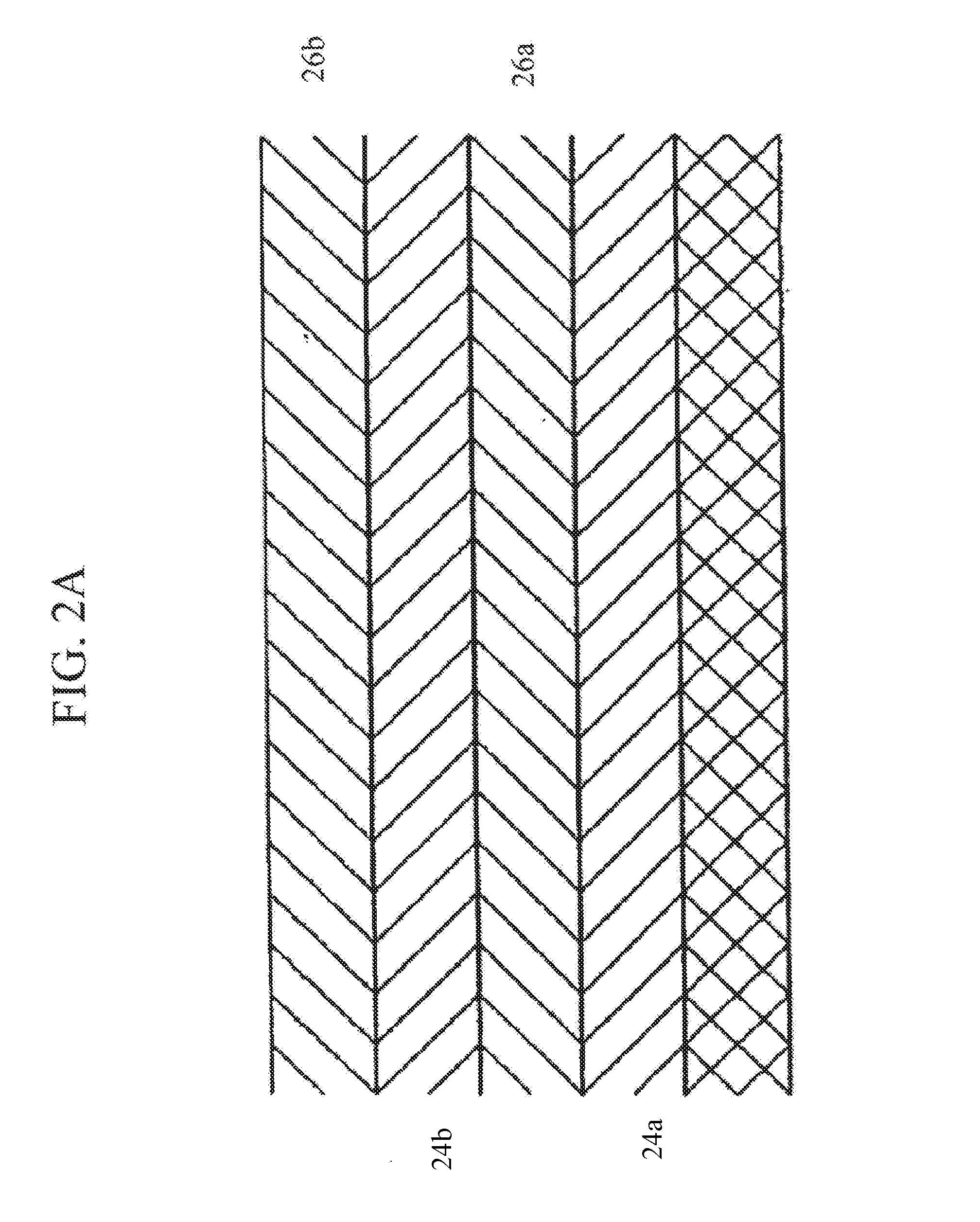
Deposition of a 2-Segment Microlaminated Ti / TiN Coatings by the LAFAD Process

[0067]A Ti / TiN microlaminated coating was deposited by an LAFAD process on 1″×1″×⅛″ square coupons made of Ti6Al4V alloy. The coupons were pre-treated by wet blasting prior to loading them in the vacuum chamber 6 of the coating system shown in FIG. 1. Only one unidirectional dual LAFAD source 2 was used in this process. Both primary cathodic arc sources 3 of the LAFAD source 2 were equipped with titanium targets. The substrate coupons 8 were installed on turntable 1 with a single rotation at a rotating speed of 12 RPM. In SR mode, the substrates are rotated around the axis of the turntable with their front surface facing the chamber walls. The coating process consists of pre-heating to 350° C., twenty minutes of ion cleaning, and two minutes of high voltage (1000V) metal ion etching; followed by coating deposition steps in a pressure range from 0.4 to 0.8 mTorr. To provide a substrate bias during the coatin...

example 3

Deposition of DLC Coating on Water Cooled Aluminum Substrates by a LAFAD Process

[0069]The DLC coatings were deposited by one unidirectional LAFAD plasma source installed in a coating system similar to that shown in FIG. 1. Aluminum disk coupons 60 mm dia×5 mm thick and aluminum strips 100 mm long×60 mm wide×5 mm thick were installed on turntable 1 attached to the water-cooled copper blocks using thermal conducting paste. An example of the curved protector airfoil 9 attached to the water cooled copper block 8 for deposition of the carbon DLC is shown schematically in FIG. 12. The copper block 8 has water inlet 10a and outlet 10b. The coating chamber was evacuated to the ultimate vacuum of 10−6 torr. Both primary cathodic arc sources 3 of the LAFAD plasma source 2 were equipped with high purity graphite targets 4. The additional anode grid made of tungsten bars ½″ thick with the distance between the bars ¾″ was installed in front of the graphite target to provide a better stability of...


PUM

PropertyMeasurementUnit
thicknessaaaaaaaaaa
widthaaaaaaaaaa
thicknessaaaaaaaaaa

Abstract

A wear resistant coating protects against corrosion and erosion of the thin metal protective sheath on turbomachinery applications. The coating has a metal layer overlaid by a ceramic layer. Multiple metal and ceramic layers can make up the coating with the layers varying in thickness allowing the layers nearer the substrate to remain more malleable to bend with the sheath and those layers nearer the top of the coating to be more brittle and resistant to wear. A cold spray metallic layer applied to the substrate provides a lightweight, flexible layer beneath the corrosion and erosion resistant protective multilayer coating.

Description

STATEMENT REGARDING FEDERALLY SPONSORED RESEARCH OR DEVELOPMENT[0001]The subject invention was made with government support under a research project supported by United States Department of Defense Contract No. W911NF-05-2-0016. The government has certain rights in this invention.CROSS-REFERENCE TO RELATED APPLICATIONS[0002]Not applicable.REFERENCE TO SEQUENCE LISTING, A TABLE, OR COMPUTER PROGRAM LISTING COMPACT DISC APPENDIX[0003]Not Applicable.FIELD OF THE INVENTION[0004]The present invention relates to coated metal sheets to protect against abrasion and erosion wear, corrosion, high temperature oxidation, and other types of surface born degradation, and also relates to the method of making the protective coatings on metal sheets and various applications of metal sheets with protective coatings, and more particularly to covers for helicopter rotors.BACKGROUND OF THE INVENTION[0005]The rotorblades of modern helicopters are made of composite materials and suffer from wear due to sa...

Claims


Application Information

Patent Timeline
Patent Type & Authority Patents(United States)
IPC IPC(8): F01D5/14F01D5/00F01D5/28F01D5/12
CPCF01D5/28F01D5/141F01D5/286F01D5/147F01D5/12F01D5/284F01D5/288F01D5/00C23C28/322C23C28/34C23C28/343C23C28/36C23C28/44Y02T50/60
Inventor GOROKHOVSKY, VLADIMIRCHAMPAGNE, VICTOR K.
Owner UNITED STATES OF AMERICA THE AS REPRESENTED BY THE SEC OF THE ARMY
Why Eureka
Try Eureka