High durability solar absorptive coating and methods for making same

Active Publication Date: 2016-11-22
NAT TECH & ENG SOLUTIONS OF SANDIA LLC
View PDF8 Cites 14 Cited by
  • Summary
  • Abstract
  • Description
  • Claims
  • Application Information

AI Technical Summary

Benefits of technology

The present invention relates to durable coatings that have high solar absorptivity. These coatings are made by thermal spraying ceramic materials (e.g., chrome oxide and lanthanum strontium manganite) and then using a laser to modify them. The laser treatment resulted in the formation of unique nanostructures on the surface of the coatings, which scatter photons and improve solar absorption. The resulting coatings have high potential for use in concentrating solar power systems and have been found to have similar figures of merit to the leading solar absorptive coating.

Problems solved by technology

Pyromark®-2500, a leading solar absorptive coating, exhibits high solar absorptivity but has limited durability as it is based on an organic resin.

Method used


Image

  • High durability solar absorptive coating and methods for making same
  • High durability solar absorptive coating and methods for making same
  • High durability solar absorptive coating and methods for making same

Examples


example 1

Solar Absorptive Coatings with Femtosecond and Nanosecond Laser Treatment

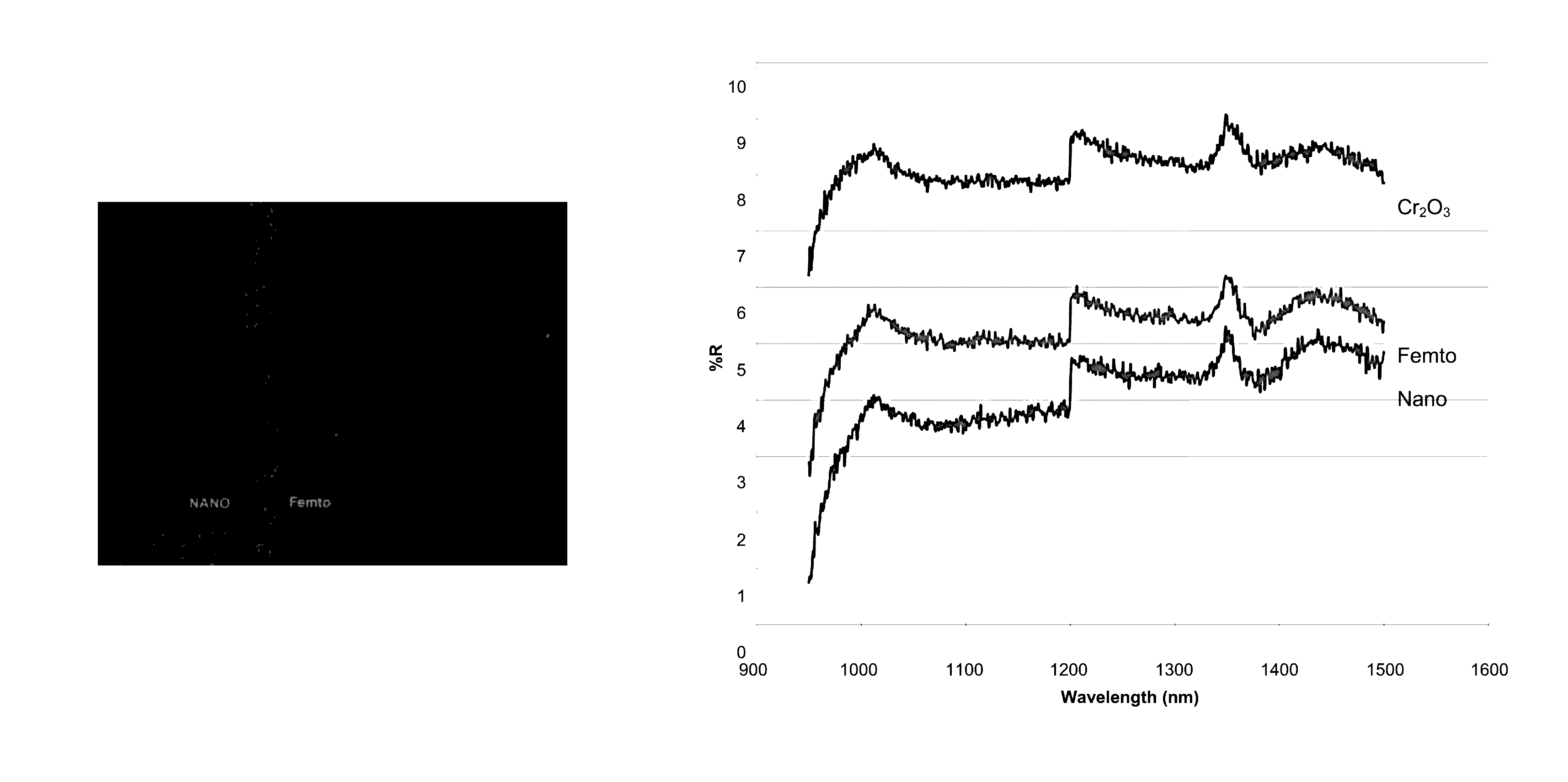
[0085]The present invention relates to solar absorptive coatings formed by laser treatment. Here, we compare treatment with a femtosecond laser and a nanosecond laser. Results of these experiments are provided in FIG. 1A-1B.

[0086]The femtosecond laser treated sample shown in FIG. 1A-1B was treated using an 800 nm Spectra-Physics® laser capable of 100 Femtosecond pulsed output at 1 khz pulse frequency. The laser was operated at the following conditions: 16 mW laser power, 1 kHz pulse rate, 1 mm / s traverse rate, 5× objective lens, and a 0.010 mm×0.010 mm raster pattern. The laser-treatment was conducted in an evacuated chamber at pressures ranging from 500 mTorr-6 Torr.

[0087]In an effort to reduce the time required for laser treatment, a nanosecond laser equipped with an optical scanning head was used. The femtosecond laser used herein had a fixed beam path and was not equipped with an optical scanning head. Lase...

example 2

Nanostructured Ceramic Surfaces for Application to Central Power Tower Receivers

[0091]Analysis of plasma sprayed Cr2O3 and LSM coatings modified using laser surface treatment are discussed. Both laser-treated coatings exhibited solar absorptivity figures of merit similar to Pyromark®-2500, the industry standard SPT receiver coating. Identifying the mechanism for the high figure of merit is critical to successfully evaluating the coating's long term high temperature performance.

[0092]Thermal spray coating processes prepare thick (>25 microns) metal and ceramic coatings via droplet deposition. A feed stock material, typically powder, is melted and propelled toward the substrate. When the feed stock droplets impact, they deform, solidify, and build a coating. Unlike other coating technologies, thermal spray processes allow rapid coating of large substrates without a vacuum chamber.

[0093]Just as many different welding process exist (e.g. laser welding, electron beam welding, and shielde...

example 3

Aging Studies of as-Sprayed and Laser-Treated Coatings

[0158]Two surfaces were further analyzed in an aging study: (1) an as-sprayed LSM coating and (2) a laser-treated LSM coating. Thermal testing, as described below, has proven that LSM surface structures and optical properties are reasonably stable at temperatures up to 700° C. for up to 20 days.

[0159]Experimental Procedures

[0160]Thermal spray coating preparation: Coatings were prepared as described herein, e.g., in Example 2. In brief, all coatings were prepared using a TriplexPro®-210 air plasma spray torch outfitted with a Unicoat™ process controller and a 9MP-CL powder hopper (Sulzer-Metco, Inc. Westbury, N.Y.). The spray torch was mounted on an ABB IRB-6600 six axis robot, which controlled the spray path (raster pattern with a traverse speed of 800 mm / s) and standoff distance (about 152.4 mm). Coatings were prepared using a standard 9 mm nozzle and 1.8 mm powder injector (powder feed rate of 30 g / min, carrier gas of argon, fe...


PUM

PropertyMeasurementUnit
Lengthaaaaaaaaaa
Lengthaaaaaaaaaa
Lengthaaaaaaaaaa

Abstract

The present invention relates to solar absorptive coatings including a ceramic material. In particular, the coatings of the invention are laser-treated to further enhance the solar absorptivity of the material. Methods of making and using such materials are also described.

Description

CROSS-REFERENCE TO RELATED APPLICATION[0001]This application claims the benefit of U.S. Provisional Application No. 61 / 945,407, filed Feb. 27, 2014, which is hereby incorporated by reference in its entirety.STATEMENT OF GOVERNMENT INTEREST[0002]This invention was made with Government support under contract no. DE-AC04-94AL85000 awarded by the U.S. Department of Energy to Sandia Corporation. The Government has certain rights in the invention.FIELD OF THE INVENTION[0003]The present invention relates to high durability solar absorptive coatings, as well as methods of making such coatings. In particular, the coatings include a ceramic oxide that is laser-treated to form a solar absorptive nanostructure. Methods of making and using such coatings are also described.BACKGROUND OF THE INVENTION[0004]Concentrating solar power (CSP) systems represent a zero emission method to convert sunlight into electricity. Generally, CSP systems use an array of mirrors to heat a working fluid by concentra...

Claims


Application Information

Patent Timeline
IPC IPC(8): F21V9/04C23C14/08C23C16/44C23C16/40C23C14/34C23C14/35C23C14/22C23C14/06C09D5/32G02B5/26F21V9/06G02B5/22G21H5/00C08J7/18B05D3/00B05D5/06
CPCC09D5/32C23C14/22C23C14/0688C23C14/08C23C16/44C23C16/40C23C14/34C23C14/35C23C4/18C23C4/11C23C4/134F24S70/225Y02E10/40
Inventor HALL, AARON C.ADAMS, DAVID P.
Owner NAT TECH & ENG SOLUTIONS OF SANDIA LLC
Why Eureka
Try Eureka