Fast quench reactor and method

a reactor and fast technology, applied in the field of fast quench reactor and method, can solve the problems of high cost, relatively low titanium utilization, and shortfall in sponge availability, and achieve the effect of minimizing back reactions and rapid cooling

Inactive Publication Date: 2002-09-24
BATTELLE ENERGY ALLIANCE LLC
View PDF37 Cites 249 Cited by
  • Summary
  • Abstract
  • Description
  • Claims
  • Application Information

AI Technical Summary

Benefits of technology

This invention relates to a reactor and method for producing desired end products by injecting reactants into the inlet end of a reactor chamber; rapidly heating the reactants to produce a hot reactant stream which flows toward the outlet end of the reactant chamber, the reactor chamber having a predetermined length sufficient to effect heating of the reactant stream to a selected equilibrium temperature at which the desired end product is available within the reactant stream as a thermodynamically stable reaction product at a location adjacent to the outlet end of the reaction chamber; passing the gaseous stream through a restrictive convergent-divergent nozzle arranged coaxially within the remaining end of the reactor chamber to rapidly cool the gaseous stream by converting thermal energy to kinetic energy as a result of adiabatic and isentropic expansion as it flows axially through the nozzle and minimizing back reactions, thereby retaining the desired end product within the flowing gaseous stream; and subsequently cooling and slowing the velocity of the desired end product and remaining gaseous stream exiting from the nozzle. Preferably the rapid heating step is accomplished by introducing a stream of plasma arc gas to a plasma torch at the inlet end of the reactor chamber to produce a plasma within the reactor chamber which extends toward its outlet end.

Problems solved by technology

Unfortunately, the widespread use of titanium has been severely limited by its high cost.
The magnitude of this cost is a direct consequence of the batch nature of the conventional Kroll and Hunter processes for metal production, as well as the high energy consumption rates required by their usage.
The combined effects of the inherent costs of such processes, the difficulty associated with forging and machining titanium and, in recent years, a shortfall in sponge availability, have contributed to relatively low titanium utilization.
Presently, titanium sponge fines from the Kroll process are used, but a major drawback is their high residual impurity content (principally chlorides), which results in porosity in the final material.
Use of such existing powders involves a number of expensive purification and alloying steps.
Although early thermodynamic calculations indicated that the reduction of titanium tetrachloride to metallic titanium of hydrogen could start at 2500 K, the system is not a simple one.
At such a high temperature, it was claimed that while titanium tetrachloride vapor is effectively reduced by atomic hydrogen, the tendency of H.sub.2 to dissolve in or react with Ti is insignificant, the HCl formed is only about 10% dissociated, and the formation of titanium subchlorides could be much less favorable.
Natural gas (where methane is the main hydrocarbon) is a low value and underutilized energy resource in the U.S. Huge reserves of natural gas are known to exist in remote areas of the continental U.S., but this energy resource cannot be transported economically and safely from those regions.
Conversion of natural gas to higher value hydrocarbons has been researched for decades with limited success in today's economy.
Supplied from domestic and foreign oil reserves to produce these petrochemical based raw materials are declining, which puts pressure on the search for alternatives to the petrochemical based feed stock.
These costly endothermic processes are operated at high temperatures and high pressures.
Development of special catalysts for direct natural gas conversion process is the biggest challenge for the advancement of these technologies.
The conversion yields of such processes are low, implementing them is costly in comparison to indirect processes, and the technologies have not been proven.
Although in commercial use, the Huels process is only marginally economical because of the relatively low single pass efficiencies and the need to separate product gases from quench gases.
Reaction cracking of the methane occurs in the narrow annular space between the tubes where the temperature is 1900 to 2100 K. In operation, carbon formation in the annulus led to significant operational problems.

Method used


Image

  • Fast quench reactor and method
  • Fast quench reactor and method
  • Fast quench reactor and method

Examples


example 1-titanium

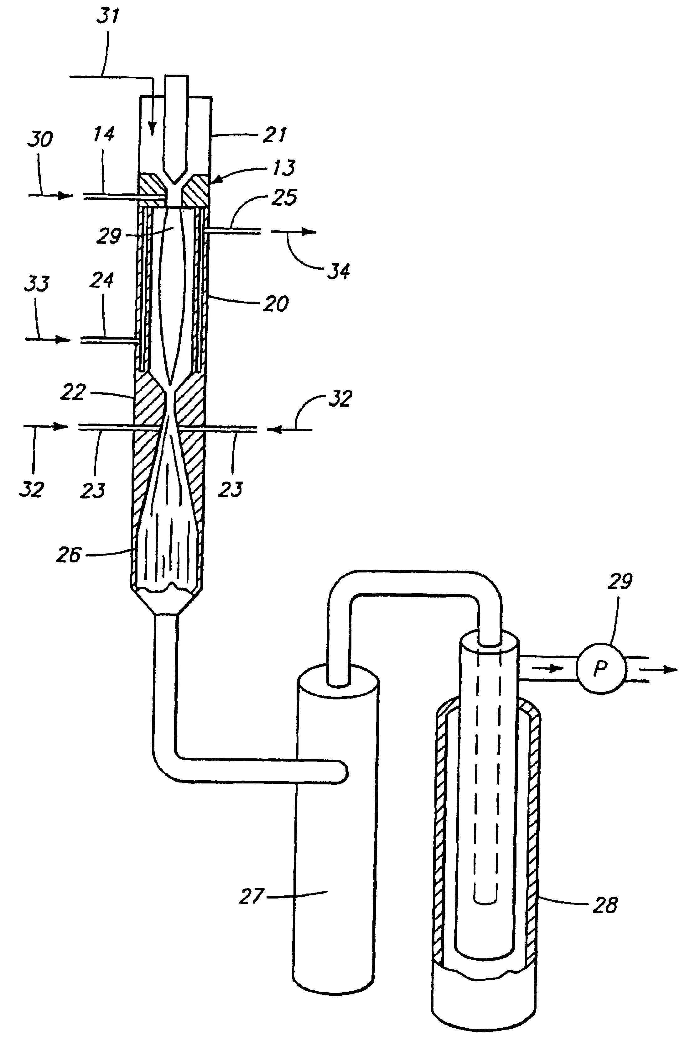
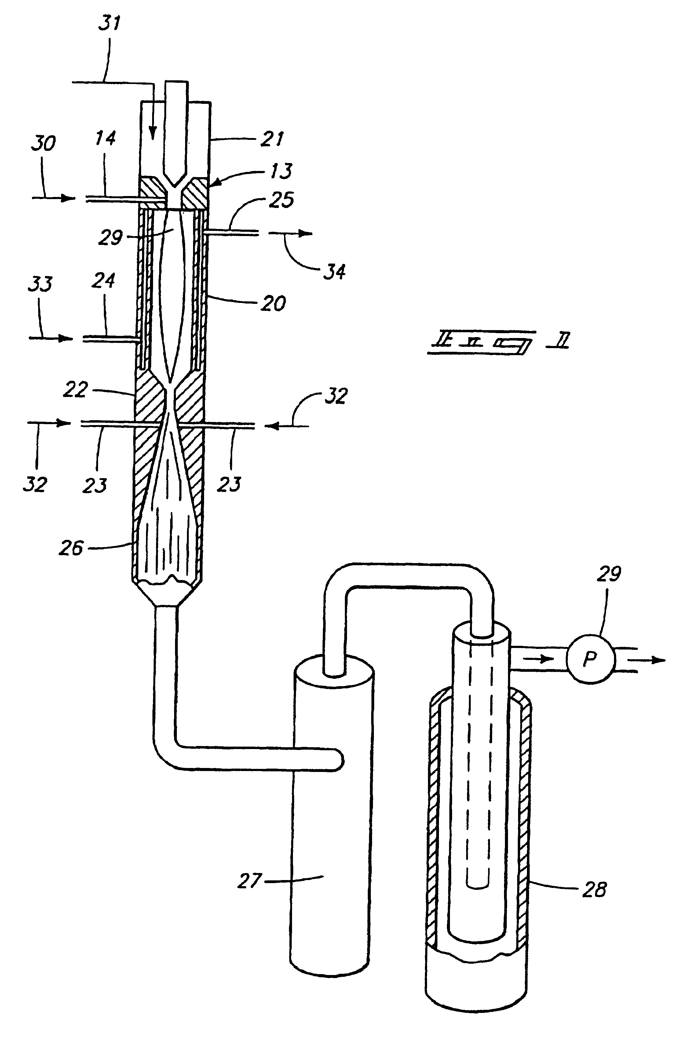
The preferred method for producing titanium from titanium tetrachloride (TiCl.sub.4 involves directing titanium tetrachloride vapor and .[.a.]. hydrogen into a hot plasma torch operated at 12 kW with a mixture of argon and hydrogen as the plasma gas (95% Argon; 5% Hydrogen, by volume) to decompose it to titanium and chlorine, followed by rapid expansion of the resulting hot gases and cooling with additional hydrogen to retain the titanium in an elemental solid metal state.

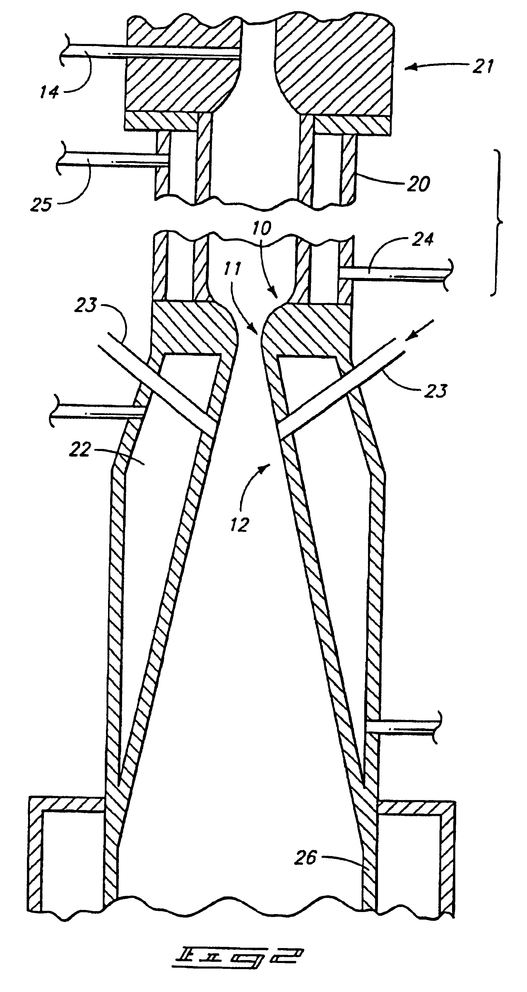
The diameter and length (6.0 mm.times.700.0 mm) of the reaction chamber was chosen to obtain maximum mixing while maintaining a minimum of 4000 K temperature at the entrance of the nozzle throat. The reaction chamber, converging / diverging nozzle were constructed from nickel 200 alloy to reduce corrosion. Standard equations were used to calculate the dimensions of the bell-shaped converging nozzle, nozzle throat diameter diverging angle, and diverging nozzle exit diameter. Reactants: Titanium tetrachloride liquid an...

example 2 -

EXAMPLE 2-TITANINUM DIOXIDE

TiO.sub.2 production in the 50 nm range can also be carried out in the existing facilities. For this purpose, TiCl.sub.4 is injected into an argon plasma and mixed with O.sub.2 just before the quench zone. Most of the TiO.sub.2 produced today is used in the paint industry and a 50 nm size (rather than the present 200 nm) is advantageous. There is also some interest in fine TiO.sub.2 as a ceramic. Preliminary results at low TiCl.sub.4 (-1 gm / hr) flow are encouraging.

The resulting titanium dioxide has a rutile structure, which has superior properties in blocking ultraviolet light. Titanium dioxide particles can be produced with average diameters of 10 nanometers or less in the narrow size ranges as defined, which can find use as a sun blocking agent for protecting human skin against harmful effects of sunlight.

The process meets all requirements for titanium production, in that it provides downstream reduction in a kinetically controlled reactor to remove hal...

example 3--

ACETYLENE

Methane conversion to acetylene in a high temperature reactor follows the theoretical chemical reaction: 2CH.sub.4.fwdarw.C.sub.2 H.sub.2 +3H.sub.2. In principle, under careful kinetic studies on the pyrolysis of methane it has been shown that it is possible to obtain high yields of acetylene where the main by-product is hydrogen, instead of tars and acetylene black. Such studies also showed that pyrolysis in the presence of hydrogen suppressed carbon formation.

In practice, a range of other hydrocarbons, specifically the light olefins and solid carbon, are always formed as byproducts with acetylene if the reaction condition is not well controlled. Equilibrium thermodynamic calculations predict a yield of acetylene at 38%, but plasma conversion experiments indicate acetylene yields are as high as 70-85%. Solid carbon formation can be as low as 10%.

Experiments using the fast quench system of this disclosure have revealed that the methane decomposition to acetylene is kinetics...


PUM

PropertyMeasurementUnit
included angleaaaaaaaaaa
temperatureaaaaaaaaaa

Abstract

A fast quench reaction includes a reactor chamber having a high temperature heating means such as a plasma torch at its inlet and a restrictive convergent-divergent nozzle at its outlet end. Reactants are injected into the reactor chamber. The resulting heated gaseous stream is then rapidly cooled by passage through the nozzle. This "freezes" the desired end product(s) in the heated equilibrium reaction stage.

Description

TECHNICAL FIELDThis disclosure pertains to equipment for thermal conversion of reactants to desired end products, which might be either a gas or ultrafine solid particles. It also relates specifically to methods for effectively producing such end products.BACKGROUND OF THE INVENTIONThe present rector and method are intended for high temperature reactions that require rapid cooling to freeze the reaction products to prevent back reactions or decompositions to undesirable products. They use adiabatic and isentropic expansion of gases in a converging-diverging nozzle for rapid quenching. This expansion can result in cooling rates exceeding 10.sup.10 K / s, thus preserving reaction products that are in equilibrium only at high temperatures.The concepts of this reactor were originally developed in a study of hydrogen reduction of titanium tetrachloride. When the concept was found to provide the high quench rates required to produce titanium, the concept was then applied to other processes ...

Claims


Application Information

Patent Timeline
Patent Type & Authority Patents(United States)
IPC IPC(8): B01J19/08B01J19/26C01B3/34C01B3/00C01B7/00C07C2/76C01B7/03C07C2/00C01G1/02C22B34/12C22B4/00C22B4/08C22B34/00C01G23/047B22F9/28C07C2/82C07C11/24C22B9/22C22B21/00C22B34/22H05H1/24
CPCB01J19/088B01J19/26B01J2219/00094B01J2219/00119B01J2219/00155B01J2219/00159B01J2219/00162B01J2219/00166B01J2219/00245B01J2219/0809B01J2219/0871B01J2219/0875B01J2219/0886B01J2219/0898B82Y30/00C01B3/342C01B7/035C01G1/02C01P2004/64C07C2/76C22B4/005C22B4/08C22B34/12C22B34/1286C22B34/129Y10S977/777H05H1/34Y02P20/582H05H1/3484C07C11/24
Inventor DETERING, BRENT A.DONALDSON, ALAN D.FINCKE, JAMES R.KONG, PETER C.
Owner BATTELLE ENERGY ALLIANCE LLC
Why Eureka
Try Eureka