Preparation process and device of sponge iron

A preparation process, sponge iron technology, applied in the direction of process efficiency improvement, furnace type, furnace, etc., can solve the problems of high preparation cost, high energy consumption per ton of iron, and no industrial application.

Inactive Publication Date: 2009-09-23
丁家伟 +1
View PDF3 Cites 41 Cited by
  • Summary
  • Abstract
  • Description
  • Claims
  • Application Information

AI Technical Summary

Problems solved by technology

However, H 2 The preparation cost is expensive, and H 2 The primary utilization rate is about 25%, the energy consumption per ton of iron is relatively high, and it is still difficult to prepare micro-nano powder in large quantities in industry, and the preparation cost is high
Under the current conditions, this achievement does not yet have industrial application

Method used


Image

  • Preparation process and device of sponge iron
  • Preparation process and device of sponge iron
  • Preparation process and device of sponge iron

Examples


Embodiment 1

[0068] Embodiment 1: the equipment scheme that the present invention solves its technical problem is:

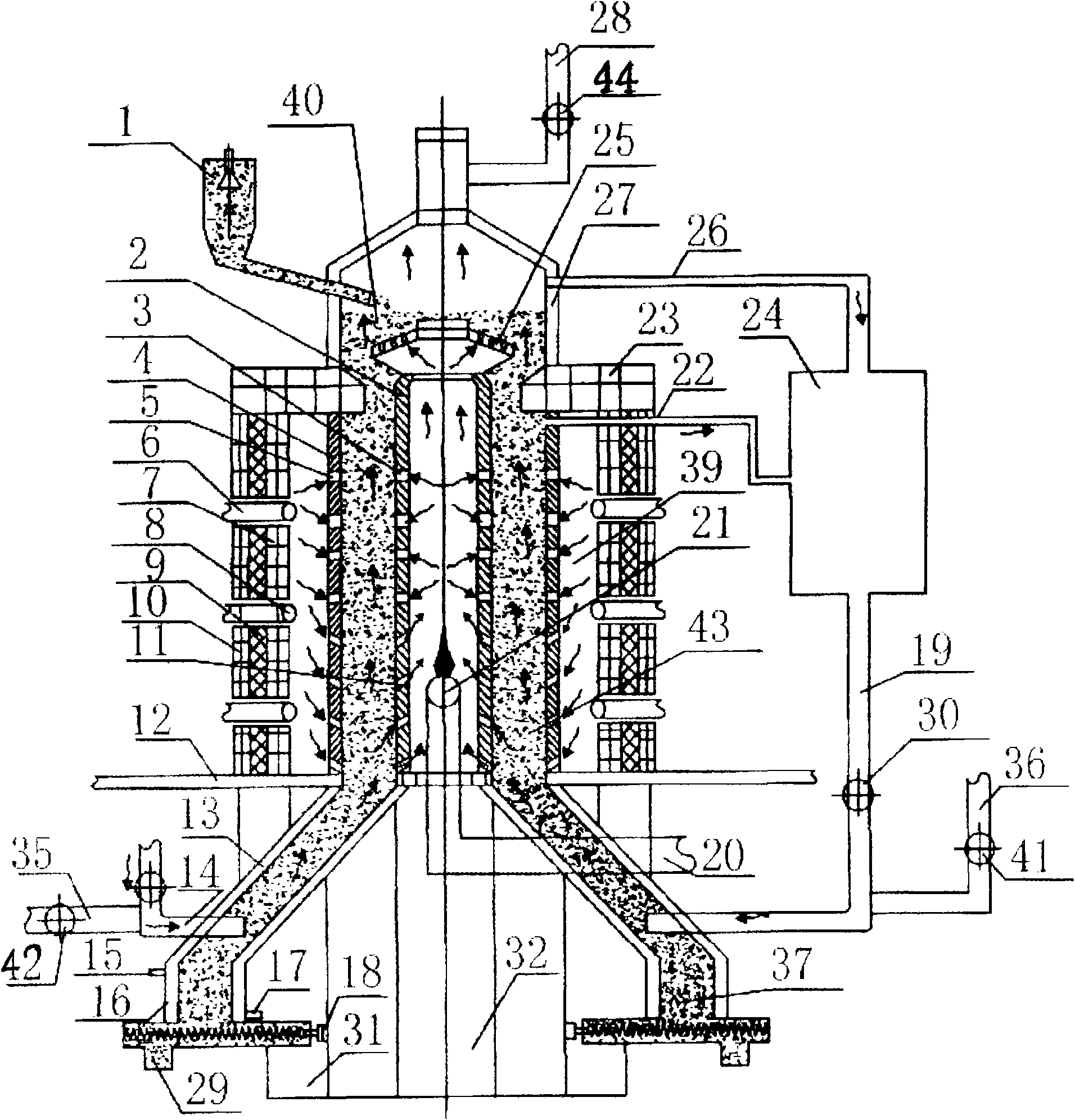
[0069] The reduction equipment includes a furnace base 12, an upper furnace body, a lower furnace body, an upper furnace cover, a drying bed furnace grate 25, a sealed blanking device 1, a purification device and a waste heat circulation device. The upper furnace body is connected with the lower furnace body under the furnace base, and the furnace cover is connected with the upper end of the upper furnace body. The drying bed furnace grate is located at the upper end of the upper furnace body. Connection, the waste heat circulation device is connected with the lower furnace body.

[0070] The upper furnace body includes an inner heating tank 2, a reducing gas outlet 3, an outer heating reduction tank 4, a heating air inlet 5, a gas pipe 6, a refractory brick 7, a gas nozzle 8, a refractory fiber 9, a reduction furnace shell 10, Intake hole 11 of inner and outer heating tank...

Embodiment 2

[0100] Embodiment 2: the equipment scheme that the present invention solves its technical problem is:

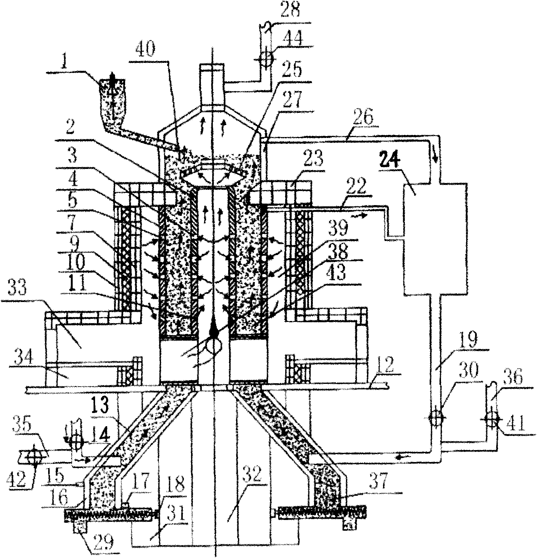
[0101] exist image 3 Among them, the upper furnace body includes an inner heating tank 2, a reducing gas outlet 3, an outer heating reduction tank 4, a heating air inlet 5, a refractory brick 7, a refractory fiber 9, a reduction furnace shell 10, and an inner and outer heating tank air inlet 11. Coal-fired combustion chamber 33, slag discharge chamber 34, internal heating flue 38, heating chamber 39, roasting reduction area 43, reduction furnace shell, refractory brick layer, external heating reduction tank and internal heating tank are set in sequence, and the reduction furnace shell Located at the outermost layer, the inner heating tank is located at the innermost layer, the coal-fired combustion chamber 33 and the slagging chamber 34 are located at the lower end of the upper furnace body, and the inner heating fire channel 38 is located at the lower end of the inner heat...

Embodiment 3

[0113] Embodiment 3: the equipment scheme that the present invention solves its technical problem is:

[0114] exist Figure 4 Among them, the upper furnace body is a porous one-channel furnace body structure, and the layout of the furnace body is a single row and one channel. In the figure, 1-1 is a heater, 1-2 is an outer furnace body, and 1-3 is an internal and external heating Reduction tanks, 1-4 are heating chambers, and each furnace body uses the same heating channel; there are 4 external heating reduction tanks and internal heating tanks distributed in the upper furnace body, and the middle and lower parts of the external heating reduction tanks and internal heating tanks There are 18 air inlets and outlets that are oblique to the vertical line of the tank body, and there are air inlets and outlets arranged parallel to the tank body in the middle and upper part of the tank body, and the air inlets and outlets are evenly distributed on the tank body; the shape of the ex...


PUM


Abstract

The invention relates to a preparation process and a device of sponge iron, belonging to metallurgical industry steel-making raw material. The process comprises the following steps: mixing iron-containing raw materials with reducing agent, solvent and catalyst to prepare ultra fine powder, passivating and mixing to make pelletizing materials, sending the prepared pelletizing materials into a reducing furnace, drying and roasting, and obtaining sponge iron after the reduction reaction. The reducing device is connected with an upper furnace above a furnace base, a lower furnace body is connected to the downside of the furnace base, the upper end of the upper furnace body is connected with an upper furnace mantle, a drying bed grate is positioned at the upper end in the upper furnace body, a purifying device is connected with the upper furnace body and the lower furnace body through pipelines, and a residual heat circulating device is connected with the lower furnace body. The invention has the advantages that: firstly, the reduction temperature is reduced, the reduction speed is increased, the energy consumption is reduced, the production cost is lowered, the production efficiency is improved, and the uniformity of the quality is ensured; secondly, the degree of mechanization is high, the procedure is simple, the yield is large, the mass production can be performed; thirdly, the waste of raw materials is lowered, the environment pollution is reduced; and fourthly, the waste resource can be recycled so as to save the resource consumption.

Description

technical field [0001] The invention relates to a metallurgical industry steelmaking raw material, in particular to a preparation process and equipment for sponge iron. Background technique [0002] Sponge iron is a metallized product obtained by reducing or deoxidizing solid iron oxide powder (usually hematite) or other iron-containing oxides by using a non-blast furnace process below the melting point of iron, usually called direct reduction Iron (DRI). During the iron ore reduction process, due to the loss of oxygen, a large number of holes are formed inside, which retains the shape of the iron ore and the gangue in the ore. Its weight is 30% less than that of iron ore, and its specific gravity is about 4.4g / cm 3 . [0003] Sponge iron is a substitute for scrap steel and pig iron. It is characterized by low carbon content (<2%), more than 90% of total iron, not only low phosphorus and sulfur content, but also does not contain copper, zinc and other impurities compare...

Claims


Application Information

Patent Timeline
Patent Type & Authority Applications(China)
IPC IPC(8): C21B13/02C22B1/242C22B1/248
CPCY02P10/20
Inventor 丁刚丁家伟
Owner 丁家伟
Why Eureka
Try Eureka