Nanotube array fuel battery of visible light response
A nanotube array and fuel cell technology, which is applied in the fields of pollution control and new energy utilization, can solve the problems of nanoparticle shedding, high photogenerated charge recombination, short electrode service life, etc., and achieves the effect of good visible light response performance.
- Summary
- Abstract
- Description
- Claims
- Application Information
AI Technical Summary
Problems solved by technology
Method used
Image
Examples
Embodiment 1
[0028] The cleaned metal titanium is used as the anode, placed in an aqueous solution containing 0.5% hydrofluoric acid, the platinum electrode is used as the counter electrode, and the voltage is adjusted to 20 V. After anodizing for 30 min, a titanium-based titanium oxide nanotube array material composed of metal titanium and titanium oxide on the titanium surface was obtained. Then the titanium-based titania nanotube array material is subjected to 450 ° After sintering at high temperature for 3 hours, TiO with anatase phase can be obtained 2 Nanotube array thin film materials.
[0029] TiO 2 The nanotube array film electrode is used as the cathode, and the platinum sheet is used as the anode. 2 and 0.1 M elemental sulfur in dimethyl sulfoxide solution, apply a bias voltage of 0.44 V, electrodeposit for 10 min, and use ultrasonic continuous ultrasonic in the whole process to obtain CdS / TiO 2 Nanotube array composite electrodes.
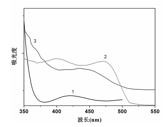
[0030] After testing three kinds of phot...
Embodiment 2
[0035] With the TiO that makes in embodiment 1 2 The nanotube array film electrode was used as the anode, Pt was used as the counter electrode, and Ag / AgCl was used as the reference electrode. A bias voltage of -0.25 V was applied in an electrolyte solution containing 0.1 M sodium acetate and 0.02 M copper acetate. The deposition process lasted for 5 min. The process uses ultrasonic continuous ultrasound to obtain Cu 2 O / TiO 2 Nanotube array composite electrodes.
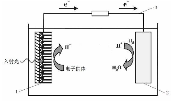
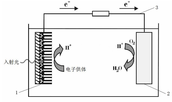
[0036] Take Cu 2 O / TiO 2 The nanotube array composite electrode is a photoanode 1 , and the platinum sheet coated with platinum black is a cathode 2 . Insert the cathode and anode into the phenol (0.05 M) solution containing 0.5 M sodium sulfate respectively, and connect them through the external circuit 3. Turn on the simulated sun light source (the light intensity is 100 mW cm -2 ) irradiates the photoanode, and continues to pass air near the cathode. At this time, phenol is oxidized near the photoanode, and...
Embodiment 3
[0038] With the TiO that makes in embodiment 1 2 The nanotube array film electrode is used as the cathode, and the platinum sheet is used as the anode. 2 and 0.1 M elemental sulfur in dimethyl sulfoxide solution, apply a bias voltage of 0.44 V, electrodeposit for 10 min, and use ultrasonic continuous ultrasonic during the whole process to obtain CdS / TiO 2 Nanotube array composite electrodes.
[0039] With CdS / TiO 2 The nanotube array composite electrode is a photoanode 1, and the platinum sheet coated with platinum black is a cathode 2. Insert the cathode and anode into the acetic acid (0.3 mM) solution containing 0.25 M sodium sulfate, respectively, and connect them through the external circuit 3. The photoanode 1 is irradiated with natural sunlight, and air is continuously introduced near the cathode 2. At this time, the acetic acid is oxidized near the photoanode, and the electrons generated are transferred to the cathode through an external circuit load, and the oxygen ...
PUM
 Abstract
Description
Claims
Application Information
 - R&D
- Intellectual Property
- Life Sciences
- Materials
- Tech Scout
- Unparalleled Data Quality
- Higher Quality Content
- 60% Fewer Hallucinations
Browse by: Latest US Patents, China's latest patents, Technical Efficacy Thesaurus, Application Domain, Technology Topic, Popular Technical Reports.
© 2025 PatSnap. All rights reserved.Legal|Privacy policy|Modern Slavery Act Transparency Statement|Sitemap|About US| Contact US: help@patsnap.com


