Method for preparing optical fiber preform rod

An optical fiber preform and preform technology, applied in glass manufacturing equipment, manufacturing tools, glass fiber products, etc., can solve the problem of complex refractive index profile and Ge/F co-doping process in-tube method, and reduce the mechanical strength of quartz melt optical fiber , Destruction of the Si-O space network structure and other issues, to achieve the effect of improving mechanical strength, low environmental load, and high deposition efficiency

Inactive Publication Date: 2012-01-18
YANGTZE OPTICAL FIBRE & CABLE CO LTD
View PDF9 Cites 14 Cited by
  • Summary
  • Abstract
  • Description
  • Claims
  • Application Information

AI Technical Summary

Problems solved by technology

However, this casing method has the following disadvantages: the large-sized casing requires high geometric accuracy, the manufacturing process is complicated, and the material loss during the casing processing leads to an increase in cost.
However, in order to prepare large preforms with low water peaks, the technical route of the extra-tube method + Soot direct outsourcing method also has the following shortcomings: As we all know, the extra-tube method is difficult to achieve complex refractive index profiles and Ge / F co-doping process and other aspects are obviously insufficient compared with the in-tube method, so the process stability is facing a huge challenge
[0007] The vapor deposition method in the prior art all uses SiCl 4 As raw material, SiCl 4 The vapor deposition method will produce highly corrosive and toxic chlorine and hydrogen chloride, the purification process is expensive, and the residual SiCl that does not participate in the reaction 4 It is difficult to recycle by hydrogenation, once it enters the environment, it will have a bad impact, and the polluted land will become barren
[0008] SiCl 4 Depositing quartz glass as a raw material will introduce Si-Cl bonds into the quartz glass material, destroying the original Si-O space network structure, causing the Si-O atomic chain to break, and macroscopically showing that the viscosity of the quartz melt is reduced and the mechanical strength of the optical fiber, which increases the probability of fiber breakage

Method used


Image

  • Method for preparing optical fiber preform rod
  • Method for preparing optical fiber preform rod
  • Method for preparing optical fiber preform rod

Examples


Embodiment 1

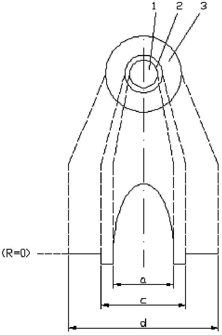
[0038] Deposit a Ge / F co-doped core layer and part of the inner cladding material in a high-purity, low-hydroxyl quartz glass liner by chemical vapor deposition in a plasma tube. The hydroxyl content of the liner is required to be less than or equal to 1000ppb, and the further requirement is less than 100ppb. A further requirement is less than 10 ppb. A liner with an outer diameter of 36 mm is used, and a mixed gas flow of silicon tetrachloride vapor, germanium tetrachloride vapor and high-purity oxygen with a proportional change is introduced into the tube from one end, and a chemical reaction is induced on the inner wall of the liner by low-pressure plasma. Thousands of thin layers of quartz glass with a thickness of micron order are formed. The above-mentioned liner containing the deposited layer is placed at a high temperature of 1900°C-2200°C to melt and shrink into a solid glass rod, which is a core rod. The deposited layer constitutes the corresponding core portion and...

Embodiment 2

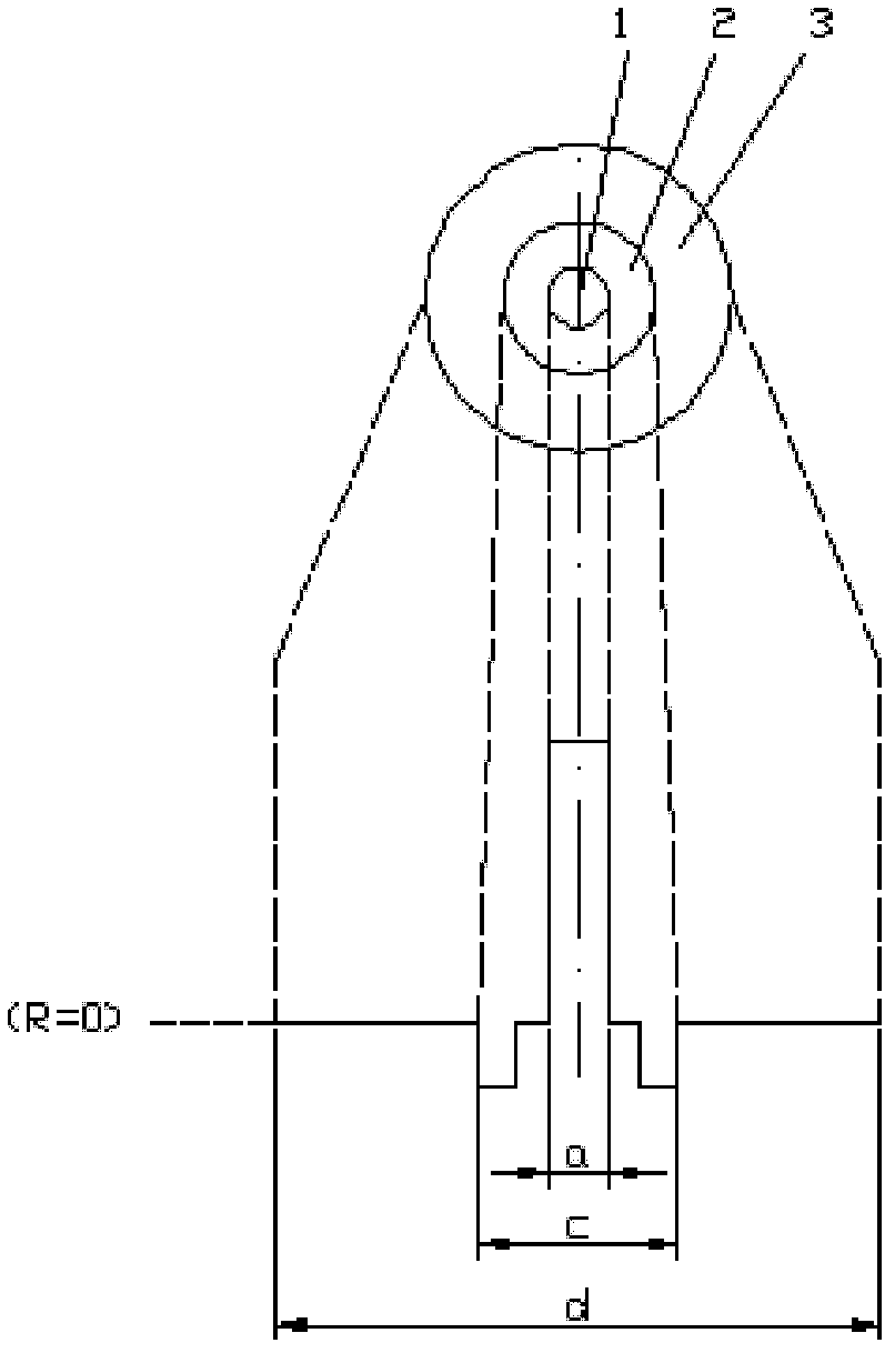
[0041] Quartz glass is deposited inside a fluorine-doped quartz tube with a relative refractive index of -0.30% and an outer diameter of 50 mm by vapor deposition. Among them, the contribution of fluorine-doped refractive index in the core layer is -0.08%, and the contribution of F-doped refractive index in the sunken cladding prepared by the in-tube method is -0.15%. In order to improve the production capacity of the mandrel, a large-size liner and a high-rate deposition process are preferred, and the length of the mandrel is 1200mm. The hydroxyl content of the liner is less than 100 ppb. From one end of the liner, a mixed gas flow of silicon tetrachloride vapor, germanium tetrachloride vapor, and high-purity oxygen that changes in proportion according to the program is introduced into the tube, and thousands of thin layers of quartz glass with a thickness of micron are formed on the inner wall of the liner. . The above-mentioned liner containing the deposited layer was pla...

Embodiment 3

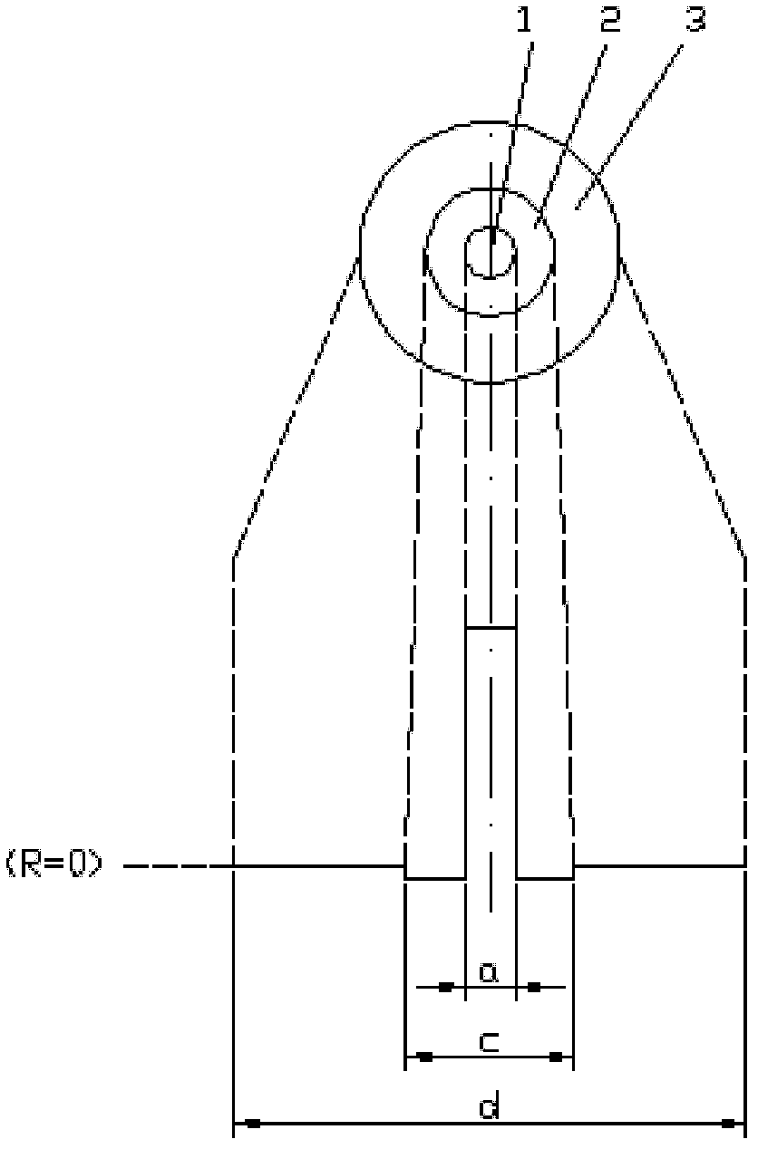
[0044] Quartz glass is deposited inside a fluorine-doped quartz tube with a relative refractive index of -0.30% and an outer diameter of 50 mm by vapor deposition. The contribution of fluorine-doped refractive index in the core layer is -0.10%, and the contribution of F-doped refractive index in the inner cladding prepared by the in-tube method is -0.11%. In order to improve the production capacity of the mandrel, a large-size liner and a high-rate deposition process are preferred, and the length of the mandrel is 1200mm. The hydroxyl content of the liner is less than 100 ppb. From one end of the liner, a mixed gas flow of silicon tetrachloride vapor, germanium tetrachloride vapor, and high-purity oxygen that changes in proportion according to the program is introduced into the tube, and thousands of thin layers of quartz glass with a thickness of micron are formed on the inner wall of the liner. . The above-mentioned liner containing the deposited layer was placed at a high...


PUM

PropertyMeasurementUnit
diameteraaaaaaaaaa
lengthaaaaaaaaaa
diameteraaaaaaaaaa

Abstract

The invention relates to a method for preparing optical fiber preform rod, which comprises the following steps: directly coating a uniform quartz loose body on an external surface of a core rod by using silane or siloxane as a raw material through an external vapor deposition method so as to form a loose-body preform rod, slowing heating the loose-body preform rod at a high temperature for dehydration, and sintering the loose-body preform rod to obtain a transparent optical fiber preform rod. The invention adopts clean silane or siloxane as a raw material for forming the quartz coating, does not generate a lot of harmful hydrogen chloride, overcomes the disadvantage that chlorine-containing raw material introduces single bonds which can block atomic bonds into the coating, increases the purity and strength of the preform rod material, and improves the mechanical strength of optical fibers.

Description

technical field [0001] The invention relates to a method for preparing an optical fiber prefabricated rod. The method comprises using silane or siloxane as a raw material to directly coat a uniform quartz soot body on the outer surface of a core rod by an external vapor deposition method to form a soot body prefabricated rod, and then Slowly heating the soot preform at high temperature for dehydration and sintering into a transparent optical fiber preform. Background technique [0002] For more than 30 years, the fiber optic manufacturing process has been continuously evolving. Optical fiber preform manufacturing technology is the core technology of the optical fiber industry. At present, the production of commercial preforms generally adopts a "two-step" manufacturing process, that is, the first step is the manufacture of mandrels; the second step is the manufacture and formation of outsourced parts. Among them, the manufacturing process of the core rod typically has an i...

Claims


Application Information

Patent Timeline
Patent Type & Authority Applications(China)
IPC IPC(8): C03B37/018
CPCC03B37/01446C03B37/01413C03B2203/22C03B2203/26C03B2207/32Y02P40/57
Inventor 罗杰曹蓓蓓倪先元
Owner YANGTZE OPTICAL FIBRE & CABLE CO LTD
Why Eureka
Try Eureka