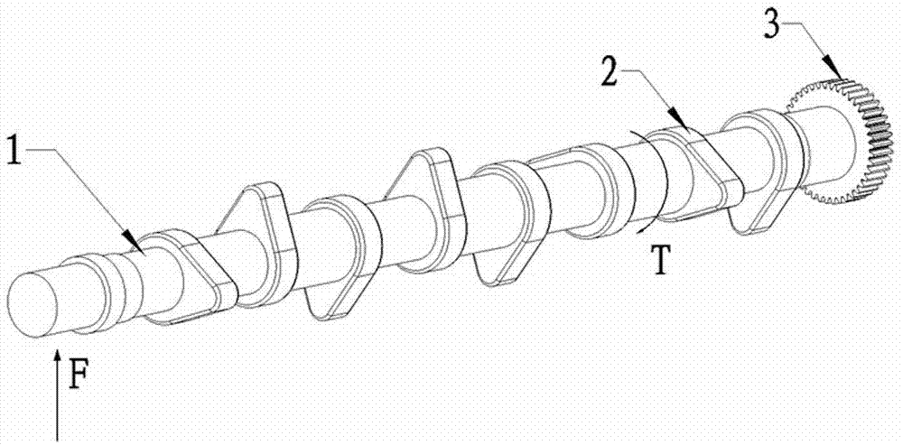
Laser cladding method for surface of automobile engine camshaft
A technology of automobile engine and laser cladding, applied in coating, metal material coating process, etc., can solve the combined impact of cam and hydraulic tappet, the increase of clearance between camshaft and bearing seat, and the clearance between driving cam and hydraulic tappet. increase, etc.
- Summary
- Abstract
- Description
- Claims
- Application Information
AI Technical Summary
Problems solved by technology
Method used
Image
Examples
Embodiment 1
[0022] A method for laser cladding on the surface of a camshaft of an automobile engine comprises the following steps:
[0023] 1) Carry out degreasing and impurity treatment on the surface of camshaft 1 at room temperature;
[0024] 2) Use CNC machine tools as the workbench;
[0025] 3) Prefabricated powder: The selected nickel-based ceramic alloy powder formula contains 16% titanium carbide, 0.6% carbon, 3% calcium fluoride, 4% silicon nitride, 15% chromium, 1.6% silicon, and 5% iron by weight percentage , 17% molybdenum, 0.8% manganese, the balance nickel and 5% indium oxide and rare earth.
[0026] 4) Clamp the camshaft 1 on the workbench and rotate it accordingly. The speed of the workbench is 300r / min, and the high-energy laser beam (that is, the spot) with a diameter of 4mm and an overlap rate of 10% passes through the fiber laser generator Axial movement is synchronized with the robot system to keep the distance from the laser beam to the surface ...
Embodiment 2
[0034] A method for laser cladding on the surface of a camshaft of an automobile engine, comprising the following steps:
[0035] 1) Degreasing the surface of the camshaft at room temperature;
[0036] 2) Use CNC machine tools as the workbench;
[0037] 3) Prefabricated powder: The selected nickel-based ceramic alloy powder formula contains 16% titanium carbide, 0.6% carbon, 3% calcium fluoride, 4% silicon nitride, 15% chromium, 1.6% silicon, and 5% iron by weight percentage , 17% molybdenum, 0.8% manganese, the balance nickel and 5% indium oxide and rare earth.
[0038] 4) Clamp the camshaft 1 on the workbench and rotate it accordingly. The speed of the workbench is 300r / min. The high-energy laser beam (ie, spot) with a diameter of 5mm and an overlap rate of 15% passes through the fiber laser generator Axial movement is synchronized with the robot system to keep the distance from the laser beam to the surface of the camshaft 1 consistent. The angle betwe...
Embodiment 3
[0046] A method for laser cladding on the surface of a camshaft of an automobile engine comprises the following steps:
[0047] 1) Degreasing the surface of the camshaft at room temperature;
[0048] 2) Use CNC machine tools as the workbench;
[0049] 3) Prefabricated powder: The selected nickel-based ceramic alloy powder formula contains 16% titanium carbide, 0.6% carbon, 3% calcium fluoride, 4% silicon nitride, 15% chromium, 1.6% silicon, and 5% iron by weight percentage , 17% molybdenum, 0.8% manganese, the balance nickel and 5% indium oxide and rare earth.
[0050] 4) Clamp the camshaft 1 on the workbench and rotate it accordingly. The speed of the workbench is 400r / min. The high-energy laser beam (ie, spot) with a diameter of 6mm and an overlap rate of 20% passes through the fiber laser generator Axial movement is synchronized with the robot system to keep the distance from the laser beam to the surface of the camshaft 1 consistent. The angle between the la...
PUM
 Abstract
Description
Claims
Application Information
 - R&D Engineer
- R&D Manager
- IP Professional
- Industry Leading Data Capabilities
- Powerful AI technology
- Patent DNA Extraction
Browse by: Latest US Patents, China's latest patents, Technical Efficacy Thesaurus, Application Domain, Technology Topic, Popular Technical Reports.
© 2024 PatSnap. All rights reserved.Legal|Privacy policy|Modern Slavery Act Transparency Statement|Sitemap|About US| Contact US: help@patsnap.com


