Compound for pigment
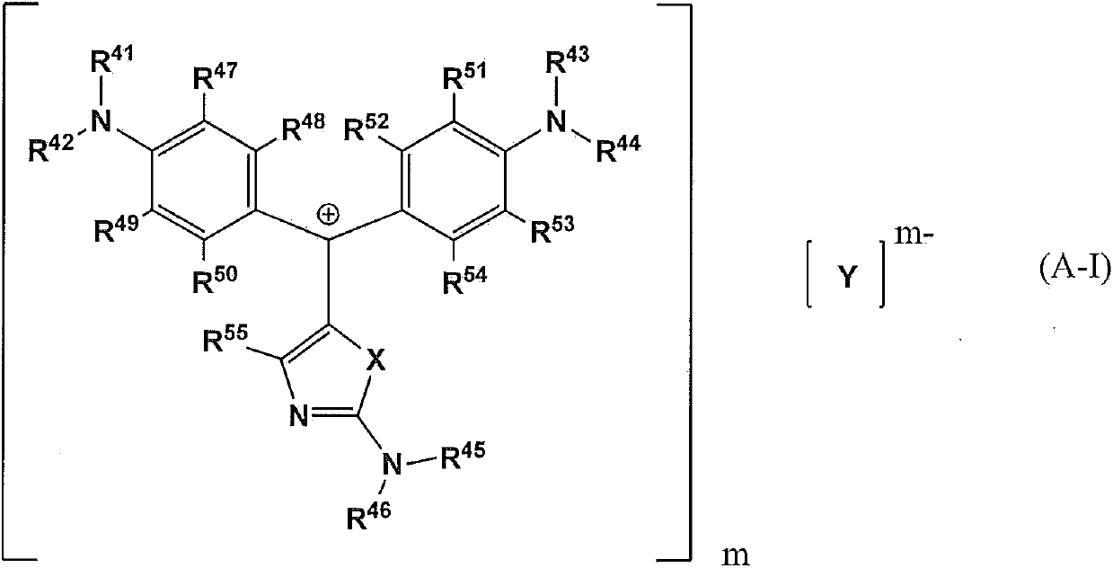
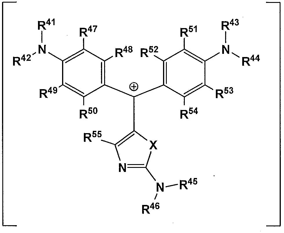
A compound and bonding technology, which is applied in the field of pigment compounds, can solve the problems of unsatisfactory heat resistance and achieve excellent heat resistance
- Summary
- Abstract
- Description
- Claims
- Application Information
AI Technical Summary
Problems solved by technology
Method used
Image
Examples
Embodiment 1
[0439] The following reactions were carried out under nitrogen atmosphere.
[0440] After putting 36.3 parts of potassium thiocyanate and 160.0 parts of acetone into the flask equipped with the cooling tube and the stirring device, it stirred at room temperature for 30 minutes. Next, 50.0 parts of benzoyl chloride (manufactured by Tokyo Chemical Industry Co., Ltd.) was dropped over 10 minutes. After completion of the dropping, the mixture was further stirred at room temperature for 2 hours. Next, after cooling the reaction mixture with ice, 45.7 parts of N-ethyl-o-toluidine (manufactured by Tokyo Chemical Industry Co., Ltd.) was dropped. After completion of the dropping, the mixture was further stirred at room temperature for 30 minutes. Next, after cooling the reaction mixture with ice, 34.2 parts of 30% sodium hydroxide aqueous solution was dripped. After completion of the dropping, the mixture was further stirred at room temperature for 30 minutes. Next, 35.3 parts of c...
Synthetic example 1
[0453] An appropriate amount of nitrogen gas was introduced into a flask equipped with a reflux cooler, a dropping funnel, and a stirrer to form a nitrogen atmosphere, 100 parts of propylene glycol monomethyl ether acetate was charged, and heated to 85° C. while stirring. Next, the following solution was dripped into the flask over a period of about 5 hours using a drip pump: 19 parts of methacrylic acid, acrylic acid-3,4-epoxytricyclo[5.2.1.0 2,6 ]decane-8-yl ester and acrylate-3,4-epoxytricyclo[5.2.1.0 2,6 171 parts of a mixture of ]decane-9-yl esters (the molar ratio is 50:50) (trade name "E-DCPA", manufactured by Daicel Co., Ltd.) is dissolved in 40 parts of propylene glycol monomethyl ether acetate solution formed in. On the other hand, the following solution was dripped into the flask over about 5 hours using another drip pump: 26 parts of the polymerization initiator 2,2'-azobis(2,4-dimethylvaleronitrile) A solution dissolved in 120 parts of propylene glycol monomethy...
Synthetic example 2
[0469] Take 250.4 parts of propylene glycol monomethyl ether acetate into a flask equipped with a stirring device, a dropping funnel, a capacitor, a thermometer, and an air duct, and stir while replacing it with nitrogen, and raise the temperature to 120°C. Next, in a mixture of 37.4 parts of methacrylic acid, 61.3 parts of benzyl methacrylate, 18.5 parts of glycidyl methacrylate, and monomethacrylate having a tricyclodecane skeleton (FA-513M manufactured by Hitachi Chemical Co., Ltd. ) 19.2 parts of the monomer mixture was added 6.13 parts of tert-butyl hydroperoxide (Perbull O manufactured by NOF Co., Ltd.). This material was dripped into the flask from the dropping funnel over 2 hours, and further, stirring was continued at 120 degreeC for 2 hours, and aging was performed. Next, the inside of the flask was replaced with air, and 10.6 parts of acrylic acid, 0.9 parts of tris(dimethylaminomethyl)phenol (DMP-30) and 0.145 parts of hydroquinone were put into the above-mentioned...
PUM
 Abstract
Description
Claims
Application Information
 - R&D
- Intellectual Property
- Life Sciences
- Materials
- Tech Scout
- Unparalleled Data Quality
- Higher Quality Content
- 60% Fewer Hallucinations
Browse by: Latest US Patents, China's latest patents, Technical Efficacy Thesaurus, Application Domain, Technology Topic, Popular Technical Reports.
© 2025 PatSnap. All rights reserved.Legal|Privacy policy|Modern Slavery Act Transparency Statement|Sitemap|About US| Contact US: help@patsnap.com


