A kind of preparation method and application of graphene-coated metal nanoparticle catalyst

A technology coated with metal nanoparticles and graphene, applied in chemical instruments and methods, physical/chemical process catalysts, nanotechnology, etc., can solve the problems of easy agglomeration of metal nanoparticles, poor stability of Pt-based electrocatalysts, and low degree of graphitization and other problems, to achieve the effect of simple and effective operation method, conducive to large-scale production, and simple preparation process

Inactive Publication Date: 2017-10-17
DALIAN UNIV OF TECH
View PDF2 Cites 0 Cited by
  • Summary
  • Abstract
  • Description
  • Claims
  • Application Information

AI Technical Summary

Problems solved by technology

However, the commercialization of low-temperature fuel cells still faces certain challenges, one of which is the slow kinetics of the cathode oxygen reduction (ORR) process.
At present, carbon-supported platinum and platinum alloy catalysts are the best performance and most widely used oxygen reduction catalysts for fuel cells, but Pt-based electrocatalysts are poor in stability and high in price, which limits the large-scale commercialization of fuel cells, so the development has high Catalysts with catalytic activity and stability, corrosion resistance and low cost have important practical significance and application value
[0003] Metal-nitrogen-carbon materials are considered to be the most promising non-precious metal ORR electrocatalysts, but there are still some problems: unreasonable structures or easy agglomeration make metal-nitrogen-carbon materials unevenly dispersed, which limits the catalytic performance. The loading of active metal-nitrogen-carbon materials reduces the overall nitrogen density of the material and reduces the metal utilization rate (generally only 2-5%); the degree of graphitization is low and the conductivity is poor; the small specific surface area makes ORR The mass transfer efficiency is low; more importantly, the active sites of ordinary metal-nitrogen-carbon materials are easily corroded in the electrolyte solution, thereby reducing the catalytic activity and life of the catalyst
However, the preparation method has poor reproducibility, metal nanoparticles are easy to agglomerate, and have poor catalytic performance for ORR.

Method used


Image

  • A kind of preparation method and application of graphene-coated metal nanoparticle catalyst
  • A kind of preparation method and application of graphene-coated metal nanoparticle catalyst
  • A kind of preparation method and application of graphene-coated metal nanoparticle catalyst

Examples


Embodiment 1

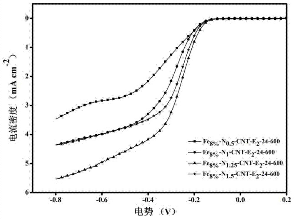
[0036] Example 1: Fe 8% -N 0.5 -CNT-E 2 -24-600 (Fe 8% Refers to the mass content of Fe in the material is 8%, N 0.5 Refers to the quality of nitrogen source melamine is 0.5 times that of carboxylated carbon nanotubes, E 2 Refers to the quality of EDTA disodium salt is twice that of iron salt, 24 refers to the hydrothermal reaction time of 24h, 600 refers to the calcination temperature of 600°C)

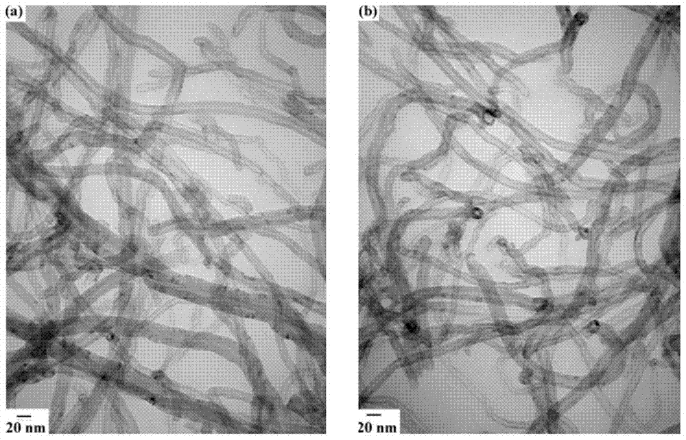
[0037] Add 0.1000g of carboxylated carbon nanotubes, 0.0386g of ferric chloride and 0.0500g of melamine to a mixed solution of 30mL of water and ethanol, ultrasonically disperse it for 30min, then magnetically stir at 50°C for 2h, then take 0.0772g of ethylenediamine Disodium tetraacetate and 10 mL of methanol were added to the above mixed solution and reacted hydrothermally at 150 °C for 24 hours, washed, filtered, and dried in vacuum at 80 °C to obtain the composite material Fe 8% -N 0.5 -CNT@EDTA-24;

[0038] Put the above materials in N 2 At 3°C ​​min under atmosphere -1...

Embodiment 2

[0039] Example 2: Fe 8% -N 1 -CNT-E 2 -24-600 (Fe 8% Refers to the mass content of Fe in the material is 8%, N 1 Refers to the quality of nitrogen source melamine is 1 times that of carboxylated carbon nanotubes, E 2 Refers to the quality of EDTA disodium salt is twice that of iron salt, 24 refers to the hydrothermal reaction time of 24h, 600 refers to the calcination temperature of 600°C)

[0040] Add 0.1000g of carboxylated carbon nanotubes, 0.0386g of ferric chloride and 0.1000g of melamine to a mixed solution of 30mL of water and ethanol, disperse it evenly by ultrasonication for 30min, then magnetically stir at 50°C for 2h, and then take 0.0772g of ethylenediamine Disodium tetraacetate and 10 mL of methanol were added to the above mixed solution and reacted hydrothermally at 150 °C for 24 hours, washed, filtered, and dried in vacuum at 80 °C to obtain the composite material Fe 8% -N 1 -CNT@EDTA-24;

[0041] Put the above materials in N 2 At 3°C ​​min under atmosph...

Embodiment 3

[0042] Example 3: Fe 8% -N 1.25 -CNT-E 2 -24-600 (Fe 8% Refers to the mass content of Fe in the material is 8%, N 1.25 Refers to the quality of nitrogen source melamine is 1.25 times that of carboxylated carbon nanotubes, E 2 Refers to the mass of EDTA disodium salt is twice that of iron salt, 24 refers to the hydrothermal reaction time of 24h, 600 refers to the calcination temperature of 600°C)

[0043] Add 0.1000g of carboxylated carbon nanotubes, 0.0386g of ferric chloride and 0.1250g of melamine to a mixed solution of 30mL of water and ethanol, ultrasonically disperse it for 30min, then magnetically stir at 50°C for 2h, then take 0.0772g of ethylenediamine Disodium tetraacetate and 10 mL of methanol were added to the above mixed solution and reacted hydrothermally at 150 °C for 24 hours, washed, filtered, and dried in vacuum at 80 °C to obtain the composite material Fe 8% -N 1.25 -CNT@EDTA-24;

[0044] Put the above materials in N 2 At 3°C ​​min under atmosphere -...


PUM


Abstract

The invention relates to a preparation method for a graphene-coated iron-loaded and nitrogen-loaded active site catalyst on a carbon nano tube (CNT); sources of raw materials used for the method are extensive; carbon source and nitrogen source materials are low in cost; the sample yield is high; the production cost of a fuel cell is helped to be reduced; the content of Fe and N in the prepared catalyst is controllable, and meanwhile, bigger specific surface area is kept so as to overcome the problem that metal nanometer particles are easy to aggregate in the past. The preparation method comprises the following steps: (1) supporting Fe and N to the surface of the carbon nano tube to obtain Fe-N-CNT; (2) synthetizing a composite material, formed by coating the surface of the Fe-N-CNT with graphene precursors, by a hydrothermal method; (3) calcining the composite material to obtain Fe-N-CNT&GN. Compared with a traditional fuel cell cathode Pt / C catalyst, the catalyst prepared by the method disclosed by the invention is low in cost, relatively higher in catalytic activity, high in stability, high in methanol tolerance, and has a good commercial application prospect.

Description

technical field [0001] The invention belongs to the technical field of energy materials and electrochemistry, and relates to a preparation method of an electrocatalyst applied to the cathode oxygen reduction reaction of a fuel cell, in particular to a metal nanoparticle catalyst coated with graphene and carried on a carbon nanotube Preparation. Background technique [0002] The depletion of fossil resources and environmental degradation continue to intensify, and the development and utilization of clean and renewable energy has become a global focus. Low-temperature fuel cell is an electrochemical reaction device that directly converts the chemical energy of fuel into electrical energy. It has the characteristics of simple structure, high theoretical energy density, and environmental protection. It has become a research hotspot of scholars at home and abroad in recent years. However, the commercialization of low-temperature fuel cells still faces certain challenges, one of ...

Claims


Application Information

Patent Timeline
Patent Type & Authority Patents(China)
IPC IPC(8): B01J21/18B01J27/24B01J35/10B82Y30/00H01M4/90
CPCY02E60/50
Inventor 李光兰刘彩娣程光春
Owner DALIAN UNIV OF TECH
Why Eureka
Try Eureka