
Microbial fuel cell and method for treating wastewater by using same

A fuel cell and microbial technology, applied in the field of sustainable biological treatment of wastewater, can solve problems such as limited oxygen solubility, weakened microbial metabolic activity, harshness, etc., achieve stable and efficient nitrogen and carbon removal, improve oxygen mass transfer efficiency, and stable performance Effect

Active Publication Date: 2016-02-03
杨凌未来中科环保科技有限公司
View PDF7 Cites 10 Cited by
  • Summary
  • Abstract
  • Description
  • Claims
  • Application Information

AI Technical Summary

Problems solved by technology

[0003] Although MFCs technology has the advantages of both pollutant removal and energy recovery, there are still some problems: 1) The dual-chamber system requires an additional diaphragm, which is likely to cause a pH gradient on both sides of the membrane and weaken the metabolic activity of microorganisms, and it is expensive, increasing the cost ( Proton exchange membrane is about 4000~12000 RMB / m 2 ); 2) In the MFCs system without diaphragm, the cathode needs to use expensive precious metals as catalysts (the price of 5% platinum carbon is 118,980 yuan / kg); 3) Potassium ferricyanide, potassium permanganate or dichromic acid Potassium and other chemical oxidants are used as electron acceptors, which have pollution and regeneration problems, which are not conducive to practical application; oxygen, as an electron acceptor, has the advantages of wide source, cheap and easy to obtain, and the product is water-free pollution, etc., but the solubility of oxygen in water is limited. Dissolved oxygen utilization efficiency is low, resulting in a large amount of aeration energy consumption
Patent No. 201020139304.3 discloses an anammox microbial fuel cell, inoculated with anammox bacteria to start the denitrification of the microbial fuel cell, although aeration is not required, but the nitrification product nitrite needs to be added as an electron acceptor, and it is anaerobic Ammonium oxidizing bacteria have the disadvantages of slow growth, being easily affected by temperature, and demanding water requirements.
Patent No. 201010166534.3 discloses a rotating biological cathode microbial fuel cell and its sewage treatment method, but the rotating biological cathode not only needs kinetic energy to drive, but also the rotation of the electrode easily entrains oxygen and transfers to the bottom anode, thereby reducing its power generation performance
Patent No. 201310745120.X discloses a preparation method of air cathode sheets of microbial fuel cells, but the preparation procedures of the diffusion layer and the catalytic layer are relatively cumbersome, which limits its practical application

Method used


Image

  • Microbial fuel cell and method for treating wastewater by using same
  • Microbial fuel cell and method for treating wastewater by using same
  • Microbial fuel cell and method for treating wastewater by using same

Examples


Embodiment 1

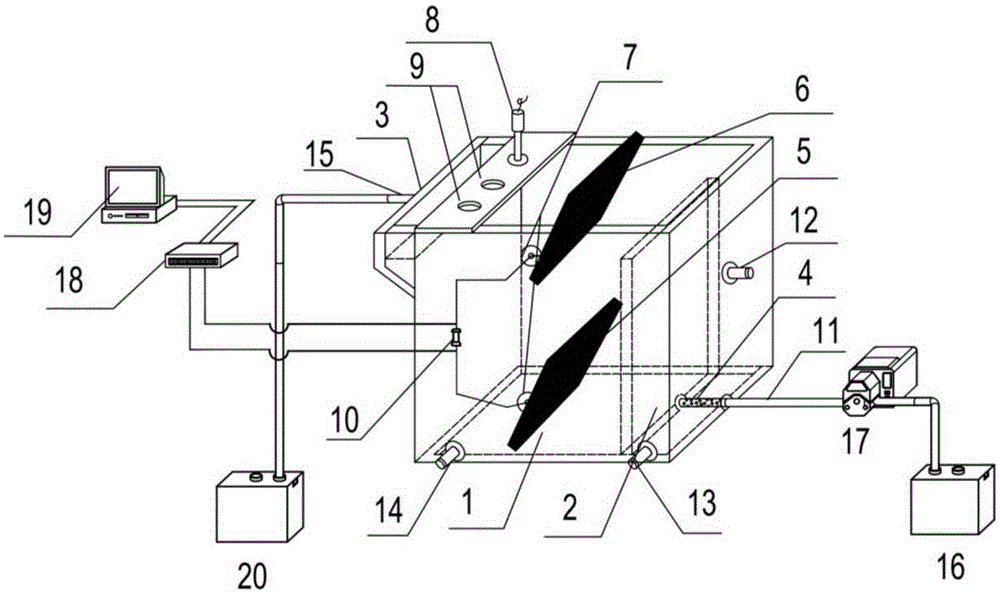
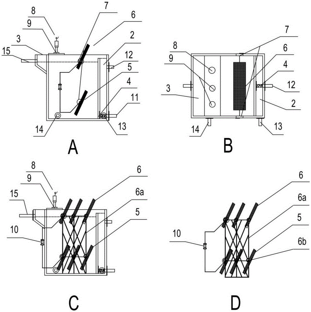
[0033] Such as figure 1 As shown, an air cathode microbial fuel cell based on capillary action includes a main reaction area 1, a biological selection adjustment area 2, an overflow outlet tank 3, a perforated water pipe 4, a biological anode 5, an air cathode 6, an electrode bracket 6a, and an electrode card slot 6b. Cathode and anode electrode socket sealing ring 7, reference electrode 8, PH and DO electrode socket 9-I and II, external resistor 10, water inlet pipe 11, monitoring port 12, emptying pipe 13 and 14, water outlet pipe 15 Composition; the main reaction zone 1 is an open columnar or cubic structure, and the electrode jacks 9-I and II are arranged on the main reaction zone 1; Part of the cathode is exposed to the air, and the area of ​​the cathode exposed to the air accounts for 1 / 4 of the entire cathode; other auxiliary equipment includes a water inlet pool 16, a peristaltic pump 17, a data acquisition card 18, a data processing and display system 19, As well as ...

Embodiment 2

[0041] The structure and operating conditions of the experimental device in this example are consistent with those in Example 1, the area of ​​the cathode exposed to air is adjusted to account for 50% of the entire cathode area, and relevant data are recorded. The result is as follows:

[0042]

[0043] As can be seen from the table, when the exposed air area of ​​the cathode accounts for 50% of the entire cathode area, the COD removal rate reaches 85-93%, and the ammonia nitrogen removal rate reaches 50-85%, which are slightly improved compared with Example 1.

Embodiment 3

[0045] In this example, the experimental device and operating conditions used were consistent with those in Example 1, and the area of ​​the cathode exposed to air was further adjusted to account for 90% of the entire cathode area, and relevant data were recorded. The result is as follows:

[0046]

[0047] It can be seen from the table that when the area of ​​the cathode exposed to air accounts for 90% of the entire cathode area, the removal rate of COD reaches 87.5-94.4%, and the removal rate of ammonia nitrogen reaches 98.7-99.9%. COD and ammonia nitrogen removal efficiency are significantly improved compared with embodiment 1 and embodiment 2.


PUM

PropertyMeasurementUnit
Electric currentaaaaaaaaaa

Abstract

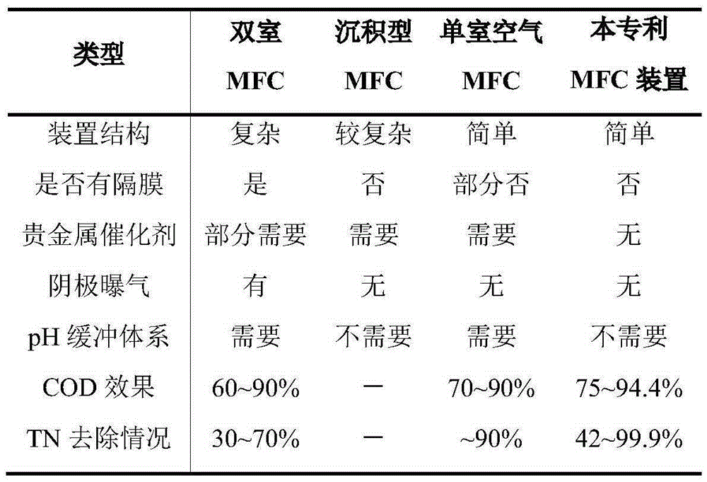
The invention relates to a microbial fuel cell and a method for treating wastewater by using the same. The microbial fuel cell comprises a main reaction zone 1, a biological selection and adjustment zone 2, an overflow water outlet trough 3, a perforated water distribution pipe 4, a biological positive electrode 5, an air negative electrode 6, an electrode support 6a, an electrode clamping slot 6b, an positive and negative electrode jack sealing ring 7, a reference electrode 8, PH and DO electrode jacks 9-I and II, an outer resistor 10, a water inlet pipe 11, a monitoring hole 12, evacuation pipes 13 and 14, and a water outlet pipe 15. According to the microbial fuel cell and the method disclosed by the invention, negative electrode aeration of the MFC (microbial fuel cell) is ingeniously avoided by using a capillary action, the energy consumption is reduced and the oxygen mass transfer efficiency of a negative electrode of the MFC is improved; stable and high-efficient denitrification and carbon removal can be realized, the COD (Chemical Oxygen Demand) removal rate can reach 75% to 94.4%, and the TN (total nitrogen) removal rate is 42% to 99.9%.

Description

technical field [0001] The invention belongs to the technical field of sustainable biological treatment of wastewater, in particular to a microbial fuel cell and a method for treating wastewater. technical background [0002] The spread of the energy and environmental crisis is becoming a major bottleneck restricting human development in the 21st century. However, with the rapid development of my country's economy, a large amount of waste water is produced every year, polluting the environment and endangering the health of residents. Pollutants in wastewater are usually discharged after traditional biological anaerobic and aerobic aeration-physical and chemical treatment, but the removal of pollutants in the above process not only consumes a lot of energy, but also produces a large amount of sludge, resulting in high treatment costs and more importantly, pollution A large amount of chemical energy contained in the food is wasted in vain. Therefore, it is urgent to develop ...

Claims


Application Information

Patent Timeline
IPC IPC(8): C02F3/34H01M8/16
CPCC02F3/34H01M8/0606Y02E60/50
Inventor 占国强杨暖李大平何晓红
Owner 杨凌未来中科环保科技有限公司
Learn More