

An electrospray ionization device and its application
A technology of electrospray ionization and conductive clips, applied in the direction of measuring devices, ion sources/guns, circuits, etc., can solve problems such as opacity, limited applications, poor biocompatibility, etc., achieve high biocompatibility, improve The effect of precision and repeatability
- Summary
- Abstract
- Description
- Claims
- Application Information
AI Technical Summary
Problems solved by technology
Method used
Image


Examples
Embodiment 1
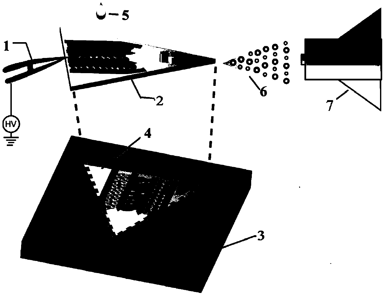
[0048] Embodiment 1 Manufacturing method and structure of electrospray ionization device
[0049] (Manufacturing of glass substrates)
[0050] Cut the cover glass with a thickness of 20 μm into an isosceles triangle with a waist length of 0.8 cm and an apex angle of 45° with a glass knife. After washing and drying, spin coat a layer on the surface at a speed of 1000 rpm The SU-82015 negative photoresist with a thickness of 30 μm was baked at 65 ° C for 20 minutes, and the mask with the microchannel pattern (the width of the microchannel was 2 mm and the number was 3) was covered on the glass slide, and the After ultraviolet exposure, development, and nitrogen blow-drying, a glass substrate with three microchannels with a width of 2 mm and a depth of 30 μm was obtained.
[0051] (Fabrication of PDMS chamber)
[0052] Mix the PDMS prepolymer and the initiator at a mass ratio of 10:1 and pour it on the silicon wafer, and seal the silicon wafer with wide tape in advance to preve...
Embodiment 2
[0054] The co-cultivation of embodiment 2 cells in microchannel
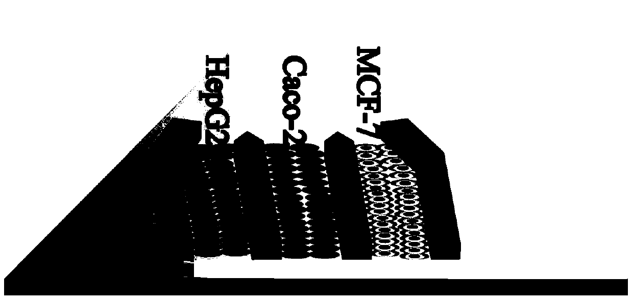
[0055] 1) Digest the human liver tumor cell HepG2, human colon adenocarcinoma cell Caco-2 and human breast cancer cell MCF-7 cells overgrown in a 60mm culture dish respectively, and dilute to 10 6 mL -1 cell suspension. 10 μL of the cell suspensions of the three types of cells were respectively added to the three microchannels placed on the glass substrate in the PDMS chamber (such as figure 2 shown), after the cells adhered to the wall, some new medium was added, and the glass substrate placed in the PDMS chamber was placed in the cell culture incubator and cultivated overnight.
[0056] 2) Take out the glass substrate from the incubator, stain HepG2, Caco-2 and MCF-7 cells with three different fluorescent dyes, Cell TrackerTM Green CMFDA, CellTrackerTM Deep Red and Cell TrackerTM Violet, and place them in the laser confocal Observed under a microscope, the results are as follows image 3 shown. It can be...
Embodiment 3
[0058] Example 3 Qualitative mass spectrometry detection of intracellular drug absorption
[0059] Co-cultivate HepG2, Caco-2 and MCF-7 cells in the same manner as in step 1) of Example 2. After culturing overnight, take out the glass substrate placed in the PDMS chamber from the incubator, and add cyclophosphamide dropwise solution (hereinafter referred to as CPA, the concentration is 10mmol / L, that is, 10mM, and the dosage is 10μL), and then put it back into the incubator, and cultivated for 24h.
[0060] The glass substrate in which MCF-7 cells were cultured in three microchannels (that is, monocultured MCF-7 cells) was used as a control sample, and its culture mode and drug action mode were the same as those of co-cultured MCF-7 cells.
[0061] Take out the glass substrate placed in the PDMS chamber from the cell culture incubator, clamp the glass substrate, and rinse it with distilled water three times to remove the complex matrix remaining on the surface of the slide. A...
PUM
| Property | Measurement | Unit |
|---|---|---|
| Width | aaaaa | aaaaa |
| Depth | aaaaa | aaaaa |
| Side length | aaaaa | aaaaa |
Abstract
Description
Claims
Application Information