
Preparation method of X-ray zone plate

A zone plate and X-ray technology, which is applied in the field of preparation of X-ray zone plates, can solve the problems such as the inability of glass filament to effectively block X-rays, the difficulty in controlling the uniformity of the annular zone, the collapse of the photoresist structure, etc., and the diffraction efficiency can be solved. Low, good graphics consistency, high aspect ratio effect

Active Publication Date: 2018-03-23
INST OF ELECTRICAL ENG CHINESE ACAD OF SCI
View PDF8 Cites 18 Cited by
  • Summary
  • Abstract
  • Description
  • Claims
  • Application Information

AI Technical Summary

Problems solved by technology

[0006] Chinese patent 201510325463.X "Preparation method of self-aligned double-layer X-ray zone plate" and 201110150368.2 "A method of manufacturing phase type zone plate" both disclose a preparation method of X-ray zone plate, but two Both of them adopt the electron beam exposure process, which is easy to cause the collapse of the photoresist structure when preparing the zone plate with large aspect ratio, and it is difficult to prepare the zone plate with large aspect ratio.
Foreign literature "Efficient focusing of 8 keV X-rays with multilayer Fresnel zone plates fabricated by atomic layer deposition and focused ion beam milling (Marcel Mayer et al., 2013)" and "Recent advances in use of atomic layer deposition and focused ion beams for fabrication of Fresnel zoneplates for hard X-rays (Kahraman Keskinbora et al., 2013)" reported the method of preparing X-ray zone plates by ALD process, but the central layer they used was glass filaments, that is, a thin film was deposited on the surface of the glass filaments, and the glass filaments could not effectively block X-rays, which make the obtained images poorer in contrast
The document "Multilayer Fresnel zone plate for high-energy x-ray by DC sputtering deposition (author S.Tamura et al., 2002)" reported the method of preparing X-ray zone plate by sputtering slicing method, but due to the use of magnetron sputtering Coating method, the minimum thickness of the film is about tens of nm, and the error is large, the uniformity control of the ring is difficult, and the filament needs to be rotated during the coating process, which increases the difficulty of preparation

Method used


Image

  • Preparation method of X-ray zone plate
  • Preparation method of X-ray zone plate
  • Preparation method of X-ray zone plate

Examples


Embodiment 1

[0025] 1. Use a tungsten wire with a diameter of 30 μm and a surface roughness of 50 nm;

[0026] 2. The given X-ray energy is 8keV, the corresponding wavelength λ=0.155nm, the focal length f=19.3548mm, the outermost ring width is 20nm, r 0 =15μm, according to the formula Calculate the number of rings in the outermost layer of the zone plate N=1801;

[0027] 3. Calculate the radius and width of each half-wave band

[0028] According to the radius of each half-wave zone according to the formula Calculated, such as r1=15.0997μm,

[0029] According to the formula Calculate the width of each half-wave band, such as △r 1 =99.7nm;

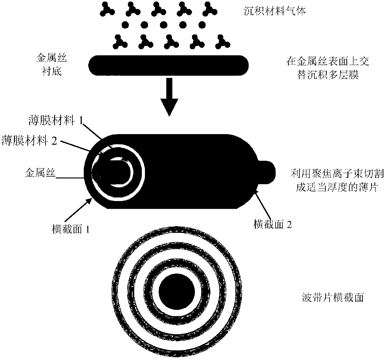
[0030] 4. Put the tungsten wire into the atomic layer deposition (ALD) coating equipment, start the equipment, and perform coating according to the calculation results in step 3. The first layer deposits aluminum oxide, and the second layer deposits hafnium oxide. 1801 layers, completed deposition;

[0031] 5. Take the coated tungsten wire out...

Embodiment 2

[0036] 1. Gold wire with a diameter of 20 μm is selected, and its surface roughness is 90 nm;

[0037] 2. The given X-ray energy is 8keV, the corresponding wavelength λ=0.155nm, the focal length f=19.3548mm, the outermost ring width is 40nm, r 0 =10μm, according to the formula Calculate the number of outermost rings of the zone plate N=436;

[0038] 3. Calculate the radius and width of each half-wave band

[0039] According to the radius of each half-wave zone according to the formula Calculated, such as r1=10.1489μm,

[0040] According to the formula Calculate the width of each half-wave band, such as △r 1 =148.9nm;

[0041] 4. Put the gold wire into the atomic layer deposition (ALD) coating equipment, start the equipment, and perform coating according to the calculation results in step 3. The first layer deposits aluminum oxide, and the second layer deposits iridium, so that the cycle is alternated until the 436th layer, to complete the deposition;

[0042] 5. Take ...

Embodiment 3

[0047] 1. Choose gold wire with a diameter of 5 μm, and its surface roughness is 70 nm;

[0048] 2. The given X-ray energy is 8keV, the corresponding wavelength λ=0.155nm, the focal length f=19.3548mm, the outermost ring width is 10nm, r 0 =2.5μm, according to the formula Calculate the number of rings in the outermost layer of the zone plate N=7498;

[0049] 3. Calculate the radius and width of each half-wave band

[0050] According to the radius of each half-wave zone according to the formula Calculated, such as r1=3.0414μm,

[0051] According to the formula Calculate the width of each half-wave band, such as △r 1 =41.4nm;

[0052] 4. Put the gold wire into the atomic layer deposition (ALD) coating equipment, start the equipment, and perform coating according to the calculation results in step 3. The first layer deposits aluminum oxide, and the second layer deposits iridium, so that the cycle is alternated until the 7498th layer, to complete the deposition;

[0053...


PUM

PropertyMeasurementUnit
diameteraaaaaaaaaa
surface roughnessaaaaaaaaaa
diameteraaaaaaaaaa

Abstract

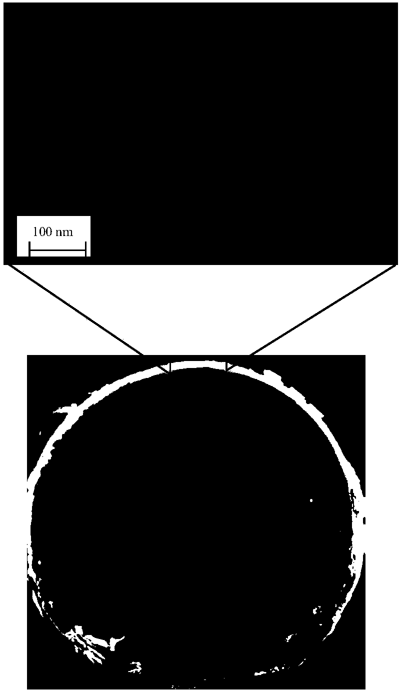
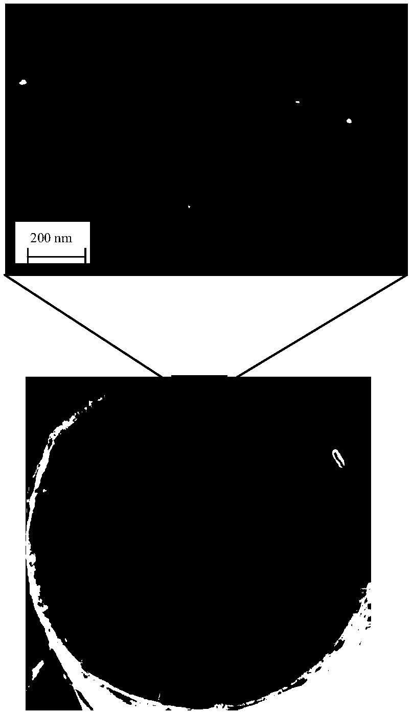
The invention relates to a preparation method of an X-ray zone plate. An atomic layer deposition (ALD) method is used to depose alumina / hafnium oxide or alumina / iridium films of different density andthickness alternatively at the surface of a metal wire whose diameter is of a micron order, namely, a first deposed alumina film layer and a second deposed hafnium oxide film or iridium film layer arearranged alternatively and cyclically to form a series of concentric circular rings. The film plated metal wire is cut and polished by focusing ion beams after film plating, and the zone plate of therequired thickness and precision is obtained. The method is suitable for preparing different types of zone plates.

Description

technical field [0001] The invention relates to a preparation method of an X-ray zone plate. Background technique [0002] X-rays have the characteristics of short wavelength and strong penetrating ability, and are widely used in space exploration, medical treatment, energy, aerospace and other fields. X-ray spectrometers and energy spectrometers are important tools for plasma diagnosis and space exploration, and X-ray diffraction optical components, which are the core components of X-ray spectrometers, have gradually become the core of the field of nano-processing, and X-ray diffraction optical components have become a modern The key to stage space exploration technology. X-ray diffraction optical components are widely used in laser inertial confinement fusion, astronomical telescopes, synchrotron radiation, EUV lithography and other fields. How to realize X-ray diffraction optical components with high resolution and high aspect ratio poses a great technical challenge for...

Claims


Application Information

Patent Timeline
Patent Type & Authority Applications(China)
IPC IPC(8): G21K1/06
Inventor 孔祥东门勇李艳丽许壮韩立
Owner INST OF ELECTRICAL ENG CHINESE ACAD OF SCI
Learn More