Device and method for improving argon recycling rate

A technology of recovery rate and argon gas, which is applied in the field of devices to improve the recovery rate of argon gas, can solve the problems of excess hydrogen gas venting, low utilization rate, failure to remove, etc., to simplify the process and operation, improve recovery rate and reduce operation The effect of energy consumption

Pending Publication Date: 2018-10-12
上海联风能源科技有限公司
View PDF3 Cites 10 Cited by
  • Summary
  • Abstract
  • Description
  • Claims
  • Application Information

AI Technical Summary

Problems solved by technology

[0004] In addition, patents have been published: for example, patent CN102583281A discloses a method and device for recovering and purifying argon in the production of single crystal silicon. The low-temperature rectification part uses air cycle refrigeration, which has high energy consumption and complicated process, and the excess hydrogen added is vented. , low utilization
For example, patent CN104406364A discloses a double-tower coupling argon recovery and purification equipment and argon recovery and purification method, which adopts air compression, double-tower process, no advantage in energy consumption, and complex structure, which increases equipment investment
Another example is that the patent CN206347802U discloses a device for reclaiming argon by single-tower low-temperature rectification, which provides a relatively large amount of external liquid argon for keeping the cold box, and is limited by regeneration gas, so the extraction rate is relatively low; and its technical scheme only uses Due to oxygen removal, the excess carbon monoxide in the raw material cannot be removed

Method used


Image

  • Device and method for improving argon recycling rate

Examples


Embodiment 1

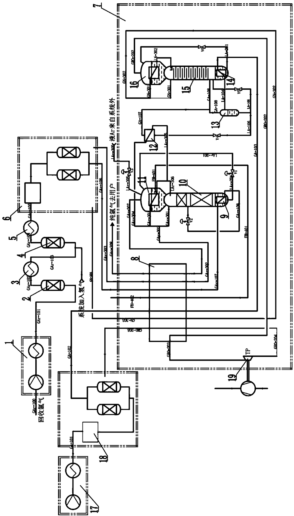
[0037] Such as figure 1 As shown, this embodiment provides a device for improving the recovery rate of argon, which specifically includes: an argon compressor 1, a carbon monoxide remover 2, an oxygen remover 4, an argon precooling and purification system 6, an air compressor 17, Air precooling and purification system 18 and rectification cold box 7, said rectification cold box 7 is built with main heat exchanger 8, argon refining tower 10 and nitrogen tower 15, and the bottom of said argon refining tower 10 is provided with argon tower and then Boiler 9, the top is provided with argon tower condensing evaporator 11, the bottom of described nitrogen tower 15 is provided with nitrogen tower reboiler 14, the top is provided with nitrogen tower condensing evaporator 16, wherein:

[0038] The argon compressor 1, the carbon monoxide remover 2, the deaerator 4 and the argon precooling purification system 6 are connected in sequence for purifying the recovered argon to remove carbon ...

Embodiment 2

[0047] This embodiment provides a method for improving the recovery rate of argon, referring to as figure 1 The flow chart shown specifically includes the following steps:

[0048] (1) After the argon gas to be recovered is purified and treated by the argon compressor 1, the carbon monoxide remover 2, the deaerator 4 and the argon precooling purification system 6, the carbon monoxide, oxygen, water and carbon dioxide in the recovered argon gas are removed , to obtain dry crude argon;

[0049] (2) Send the dry crude argon into the rectifying cold box 7, send it to the argon tower reboiler 9 at the bottom of the argon tower 10 after being cooled by the main heat exchanger 8, and get out the gas-liquid of the argon tower reboiler 9 The mixed fluid is sent to the middle and upper part of the refining argon column 10 through the pipeline through the crude argon throttling valve V2 to participate in rectification. The gas part rises with the gas in the refining argon column 10, and...

Embodiment 3

[0061] This embodiment provides a kind of application of the device that adopts the present invention to improve the recovery rate of argon, please continue to refer to figure 1 The process flow diagram shown has two parts: the main argon recovery flow path and the air nitrogen recovery flow path:

[0062] (1) Argon recovery flow path:

[0063] Argon to be recovered (O 2 2 2 、H 2 Wait.

[0064]The dry crude argon enters the rectification cold box 7 through the pipeline GAr-106, first enters the main heat exchanger 8 to cool down to the liquefaction point, passes through the pipeline GAr-107, and enters the argon column reboiler 9 set up at the bottom of the refined argon column 10 , in the argon column reboiler 9, most of the gas (80% to 95%) is liquefied, and the gas-liquid mixed fluid exiting the argon column reboiler 9 flows out from GAr-108, and is throttled through the crude argon throttle valve V2 The reduced pressure is sent to the middle and upper part of the argon...


PUM


Abstract

The invention discloses a device and method for improving the argon recycling rate. The convenience that in the recycling site, liquid argon exists and is used for providing is used, liquid argon is used for providing cold amount, a low-temperature distillation method is used for removing nitrogen and hydrogen, the argon recycling rate and the hydrogen utilization rate are improved, the flow and the operation of low-temperature distillation are simplified, and running energy consumption is reduced; an integrated air and nitrogen flow path is used, cold amount is generated through an expansionmachine, nitrogen is generated from the interior of a cold box, limitation of regeneration air flow is reduced, the extraction rate of argon recycling is improved, in addition, the connection effect of an auxiliary condensation evaporator is used, an argon recycling flow path and an air and nitrogen flow path are subject to cold exchange, redundant cold amount generated by an expanding machine isconveyed to the argon recycling flow path, the liquid argon amount added from the exterior can be reduced, and the running cost of the device can be reduced.

Description

technical field [0001] The invention relates to a method for recovering argon, in particular to a device and a method for improving the recovery rate of argon. Background technique [0002] The Czochralski method (Czochralski method) is the main method for producing single crystal silicon, and 70% to 80% of the world's single crystal silicon is produced by the Czochralski method. The most commonly used process for producing single crystal silicon by the Czochralski method is a decompression crystal pulling process that is similar to a vacuum process and a flowing atmosphere process; High-purity argon is introduced into the furnace, and the vacuum pump continuously pumps argon from the furnace to keep the vacuum in the furnace stable at about 20 torr. This process has both the characteristics of vacuum technology and the characteristics of flow atmosphere technology. Vacuum pumps for decompression crystal pulling process generally use slide valve pumps, which are mechanical ...

Claims


Application Information

Patent Timeline
Patent Type & Authority Applications(China)
IPC IPC(8): F25J3/02
CPCF25J3/0285F25J3/0295F25J3/08F25J3/0426F25J3/04284F25J3/044F25J3/04563F25J3/04612F25J3/04618F25J2200/72F25J2205/04F25J2205/40F25J2205/66F25J2205/82F25J2210/58F25J2230/30F25J2250/20F25J2270/904F25J2215/58F25J2200/50F25J2200/02F25J2260/02
Inventor 郝文炳
Owner 上海联风能源科技有限公司
Why Eureka
Try Eureka