

Vacuum film plating method with combined magnetic field, lined straight pipe and multihole baffle combined
A porous baffle and vacuum coating technology, which is applied in vacuum evaporation coating, sputtering coating, ion implantation coating, etc., can solve the problems of film composition pollution, large particle defects, low film deposition efficiency, etc., and achieve high utilization Efficiency, the effect of ensuring uniformity
- Summary
- Abstract
- Description
- Claims
- Application Information
AI Technical Summary
Problems solved by technology
Method used
Image

Examples
specific Embodiment approach 1
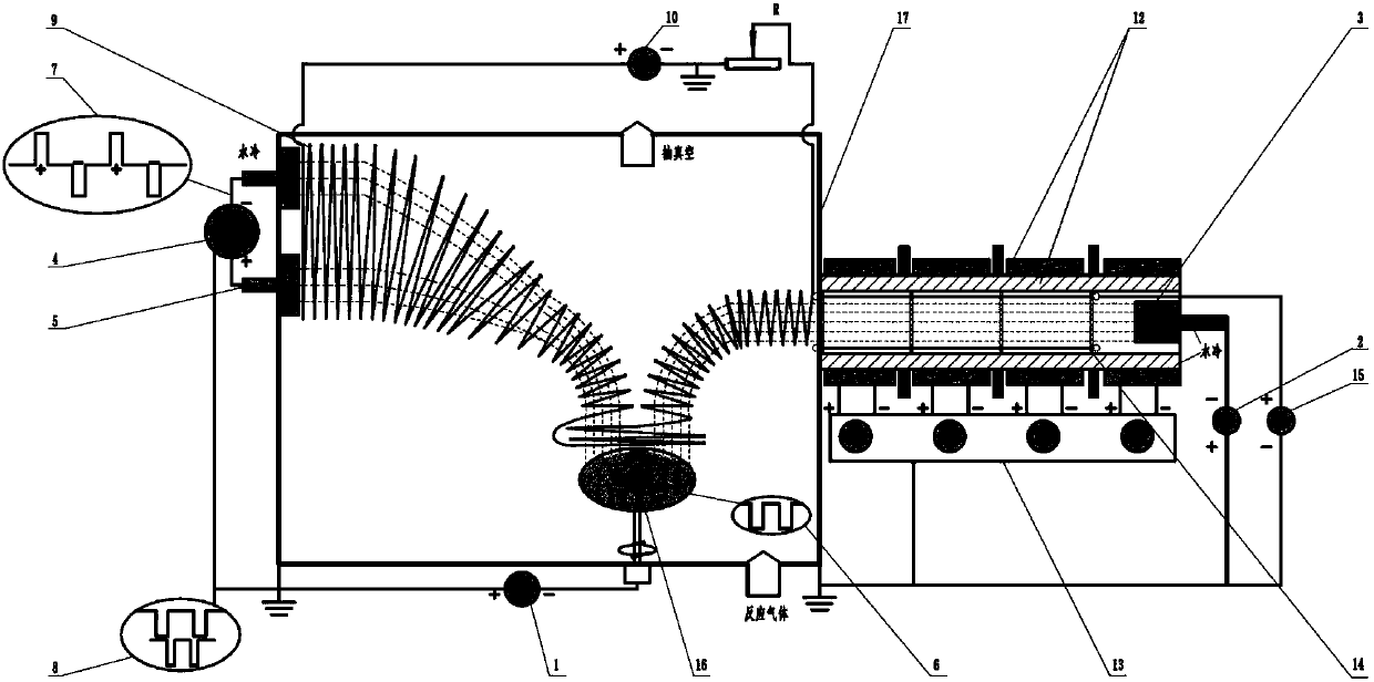
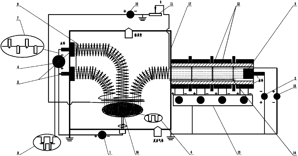
[0025] Specific implementation mode one: the following combination Figure 1-6Describe this embodiment. In this embodiment, a vacuum coating method that combines a magnetic field with a lined straight pipe and a porous baffle is used. The device includes a bias power supply (1), an arc power supply (2), an arc ion plating target source (3 ), twin target high power pulse magnetron sputtering power supply (4), twin target high power pulse magnetron sputtering target source (5), bias power waveform oscilloscope (6), twin target high power pulse magnetron sputtering power supply Waveform oscilloscope (7), waveform synchronous matching device (8), movable coil device (9), movable coil device power supply (10), rheostat device (11), multi-level magnetic field device (12), multi-level magnetic field device power supply (13 ), liner bias straight tube and porous baffle combined device (14), liner bias power supply (15), sample stage (16) and vacuum chamber (17);
[0026] In this devi...
specific Embodiment approach 2
[0044] Embodiment 2: The difference between this embodiment and Embodiment 1 is that a combined magnetic field is connected with the vacuum coating method of lining the straight pipe and the porous baffle, and the arc power supply (2) is turned on, and the multi-stage magnetic field power supply is turned on. (5) Adjust the multi-stage magnetic field device (12), turn on the lining bias power supply (15), adjust the bias voltage of the lining bias straight tube and porous baffle assembly (14), turn on the movable coil device power supply (10) to adjust The movable coil device (9) adjusts the output resistance of the rheostat device (10), and the waveform synchronous matching device (8) controls the bias power supply (1) and the twin target high-power pulse magnetron sputtering power supply (4) to be turned on simultaneously, and the twin target The period of the output pulse of the target high-power pulse magnetron sputtering power supply (4) is an integer multiple of the outpu...
specific Embodiment approach 3
[0045] Embodiment 3: The difference between this embodiment and Embodiment 1 is that a combined magnetic field is connected with a vacuum coating method in which the lined straight tube and the porous baffle are combined, the arc power supply (2) is turned on, and the multi-stage magnetic field power supply is turned on (5) Adjust the multi-stage magnetic field device (12), turn on the lining bias power supply (15), adjust the bias voltage of the lining bias straight tube and porous baffle assembly (14), turn on the movable coil device power supply (10) to adjust The movable coil device (9) adjusts the output resistance of the rheostat device (10), and the waveform synchronous matching device (8) controls the bias power supply (1) and the twin target high-power pulse magnetron sputtering power supply (4) to be turned on simultaneously, and the twin target The target high-power pulse magnetron sputtering power supply (4) outputs high-power pulses and the bias pulse waveform outp...
PUM
 Abstract
Description
Claims
Application Information