A ferrimagnetic nanomaterial and its application in magnetic particle imaging
A technology of magnetic particle imaging and nanomaterials, which can be applied to medical preparations with inactive ingredients, preparations for in vivo experiments, microcapsules, etc. Uniform and controllable imaging effect, size and shape
- Summary
- Abstract
- Description
- Claims
- Application Information
AI Technical Summary
Problems solved by technology
Method used
Image
Examples
Embodiment 1
[0031] Embodiment 1: the synthesis of cube-shaped iron ferric oxide nanoparticles
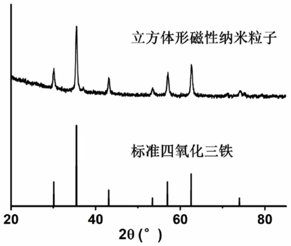
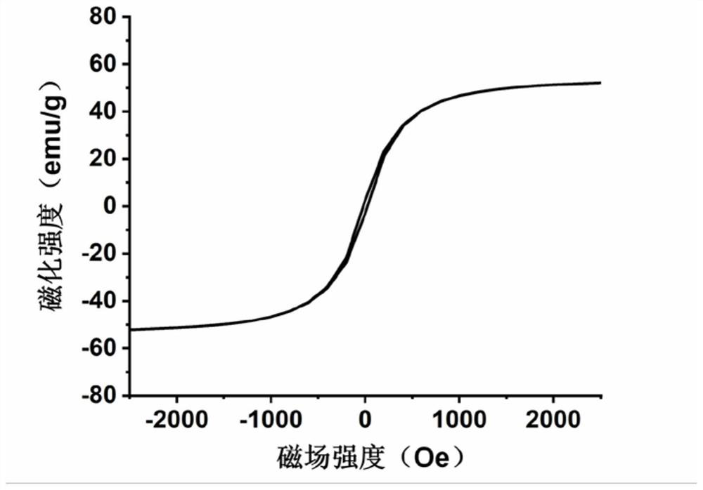
[0032] Mix 0.71 g of iron acetylacetonate with 0.4 g of biphenyl-4-carboxylic acid, 1.27 g of oleic acid, and 10.4 g of dibenzyl ether, stir at room temperature for 1 h under vacuum, and heat the mixture to 290 °C at a rate of 20 °C / min. ℃, when the temperature of the system reaches 290 ℃, keep the temperature for 30 minutes, cool it rapidly, wash the product with a 4:1 mixed solution of toluene and hexane, and then resuspend it in chloroform for storage. The particle size is 20-25nm. The X-ray diffraction result of the cube-shaped iron ferric oxide nanoparticles prepared in this embodiment is as follows figure 1 As shown, it is proved that the obtained nanoparticles are ferric oxide crystal form; the magnetization curve results are as follows figure 2 As shown, it shows that the obtained nanoparticles are ferrimagnetic, with high saturation magnetization and magnetic susceptibility, low coe...
Embodiment 2
[0033] Embodiment 2: the synthesis of cube-shaped iron ferric oxide nanoparticles
[0034] Mix 0.71g of iron acetylacetonate with 1.13g of oleic acid and 52g of dibenzyl ether, stir at room temperature for 1h under vacuum, and raise the temperature of the mixture to about 290°C at a rate of 20°C / min. When the system temperature reaches 290°C, keep The temperature was 15 minutes, cooled rapidly, the product was washed with a 4:1 mixed solution of toluene and hexane, and then resuspended in chloroform for storage. The obtained cubic iron ferric oxide nanoparticles had a size of 25-30nm.
Embodiment 3
[0035] Embodiment 3: the synthesis of ferrimagnetic nanomaterial
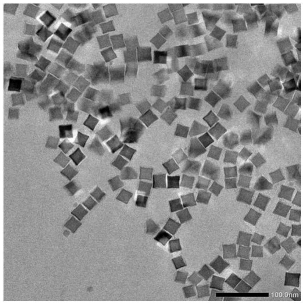
[0036] Disperse 2-5 mg of cubic iron ferric oxide nanoparticles synthesized in Example 1 and 10-50 mg of phospholipid polyethylene glycol in a mass ratio of 5:1 in 10-50 mL of chloroform. The organic solvent was evaporated under reduced pressure to form a thin film. Continue to add 2-5 mL of double distilled water for hydration to obtain monodisperse cubic magnetic nanoparticles in the aqueous phase system. The morphology of the cube-shaped magnetic nanoparticles was characterized by transmission electron microscopy, and the results are as follows: image 3 As shown, it can be seen from the figure that the synthesized nanoparticles are cubes with uniform size, and the core size is about 20-25nm.
[0037] Using dynamic light scattering to analyze the particle size distribution of cubic magnetic nanoparticles, the results are as follows Figure 4 As shown, the results prove that the cube-shaped magnetic nanopa...
PUM
| Property | Measurement | Unit |
|---|---|---|
| size | aaaaa | aaaaa |
| size | aaaaa | aaaaa |
| size | aaaaa | aaaaa |
Abstract
Description
Claims
Application Information
 - R&D
- Intellectual Property
- Life Sciences
- Materials
- Tech Scout
- Unparalleled Data Quality
- Higher Quality Content
- 60% Fewer Hallucinations
Browse by: Latest US Patents, China's latest patents, Technical Efficacy Thesaurus, Application Domain, Technology Topic, Popular Technical Reports.
© 2025 PatSnap. All rights reserved.Legal|Privacy policy|Modern Slavery Act Transparency Statement|Sitemap|About US| Contact US: help@patsnap.com


