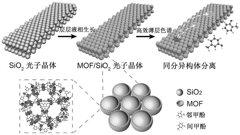
Efficient thin layer chromatographic separation method based on metal organic framework material composite photonic crystal thin layer
A technology of metal-organic frameworks and photonic crystals, applied in material separation, analytical materials, instruments, etc., can solve problems such as inability to separate, limited improvement in separation efficiency, and no reports on photonic crystal thin-layer chromatography separation technology, so as to ensure high efficiency Separation, strong adsorption and desorption effect and selectivity, and the effect of making up for poor separation effect
- Summary
- Abstract
- Description
- Claims
- Application Information
AI Technical Summary
Problems solved by technology
Method used
Image

Examples
Embodiment 1
[0080] Embodiment 1. Preparation of SiO 2 photonic crystal thin layer
[0081] use Monodisperse SiO with an average particle size of 200 nm prepared by method 2 colloidal particles. Take 80 μL of SiO 2 The colloidal particles were dispersed in 1 mL of ethanol, and 120 μL of ethylene glycol was added for ultrasonic mixing to form a homogeneous transparent solution. The mixed solution was placed in an oven at 90° C. for 2 hours to evaporate and remove the ethanol in the solution, and finally 200 μL of a colloidal supersaturated solution with a volume fraction of 40% colloidal particles was obtained. Take 30 μL of the above precursor solution and drop it on the hydrophilic glass substrate treated with piranha solution, and spread the precursor solution evenly into a liquid film with a thickness of about 100 μm by coating method. Stand at room temperature for 15 minutes. After a large number of colloidal crystals are precipitated to form liquid colloidal crystals, transfer t...
Embodiment 2
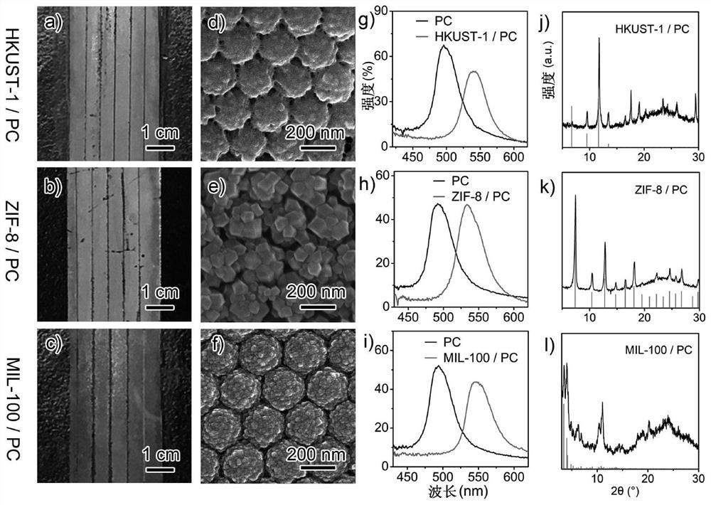
[0082] Embodiment 2. Preparation of metal-organic framework material composite photonic crystal (MOF-PC) thin layer
[0083] First, the SiO after calcined in Example 1 of the present invention 2 The photonic crystal thin layer was soaked in piranha solution for 12 hours to recover the surface hydroxyl groups. Subsequent hydroxylated SiO 2 The photonic crystal thin layer was soaked in 0.06% aminopropyltriethoxysilane (APTES) ethanol solution with a volume fraction of 0.06%, reacted at room temperature for 12 hours, was taken out and washed with ethanol and dried to obtain a photonic crystal thin layer modified with amino groups on the surface. Finally, soak the thin layer of amino-modified photonic crystals in a succinic anhydride dimethylformamide solution with a concentration of 0.005 g / mL, react at room temperature for 12 hours, wash with ethanol and dry after removal to obtain photonic crystals rich in carboxyl groups on the surface. crystal thin layer.
[0084] Thin lay...
Embodiment 3
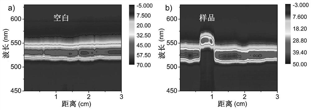
[0085] Example 3. Using spatially resolved reflectance spectroscopy to determine the position of the sample point on the photonic crystal thin-layer plate
[0086] The position of the chemical substance sample point on the MOF-PC thin-layer plate described in Example 2 of the present invention can be directly observed with the naked eye, or can be accurately determined by using spatially resolved reflectance spectroscopy (SRRS). In actual operation, the optical fiber probe of the spectrometer is usually fixed above the thin-layer chromatography plate, and the thin-layer plate is pulled along the opposite direction of the sample development at a constant rate of 2 cm / min, so that the spectrometer can continuously record the MOF-PC thin-layer plate along the sample. The direction of the spectral change. A series of spectral data is plotted as a three-dimensional reflection spectrum with the ratio shift (Rf) value on the x-axis, the reflection wavelength on the y-axis, and the re...
PUM
| Property | Measurement | Unit |
|---|---|---|
| Specific surface area | aaaaa | aaaaa |
Abstract
Description
Claims
Application Information