Method for preparing foamy carbon supported FeNi alloy catalyst from nitro-modified metal organic framework and application of foamy carbon supported FeNi alloy catalyst

A metal-organic framework and alloy catalyst technology, applied in the application field of electrocatalytic water splitting catalysts, can solve problems such as agglomeration, uneven particle distribution, and limited catalytic performance of materials, and achieve low cost, wide source of raw materials, and excellent catalytic performance. Effect

Pending Publication Date: 2022-04-08
JIANGXI NORMAL UNIVERSITY
View PDF10 Cites 0 Cited by
  • Summary
  • Abstract
  • Description
  • Claims
  • Application Information

AI Technical Summary

Problems solved by technology

However, the currently prepared FeNi-based nanomaterials often have serious agglomeration

Method used


Image

  • Method for preparing foamy carbon supported FeNi alloy catalyst from nitro-modified metal organic framework and application of foamy carbon supported FeNi alloy catalyst
  • Method for preparing foamy carbon supported FeNi alloy catalyst from nitro-modified metal organic framework and application of foamy carbon supported FeNi alloy catalyst
  • Method for preparing foamy carbon supported FeNi alloy catalyst from nitro-modified metal organic framework and application of foamy carbon supported FeNi alloy catalyst

Examples


Embodiment 1

[0034] The preparation of embodiment 1FeNi@NCF

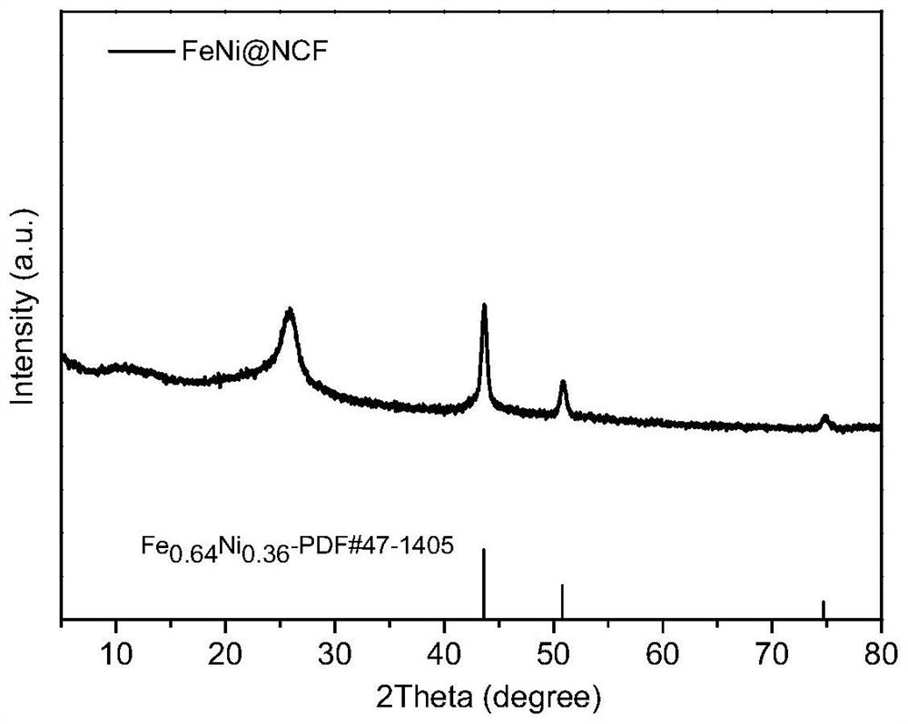
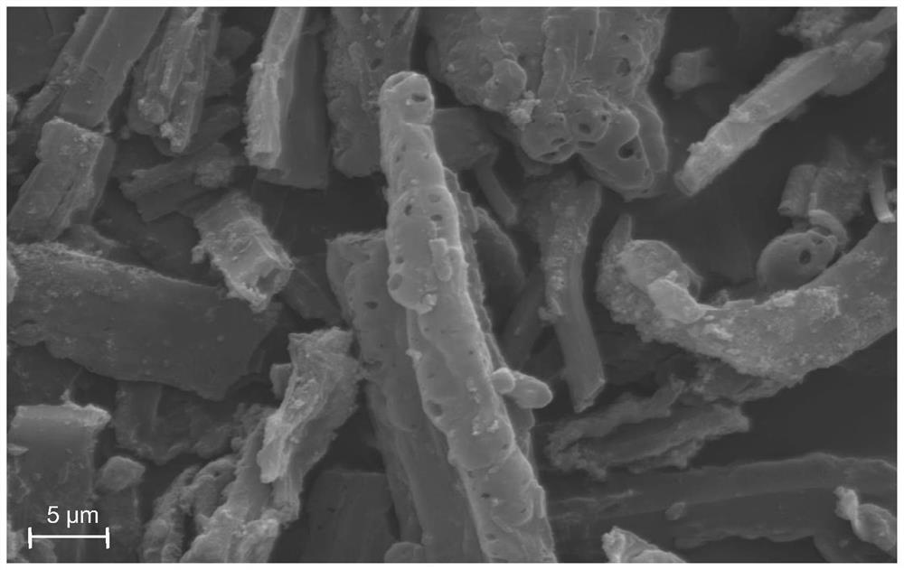
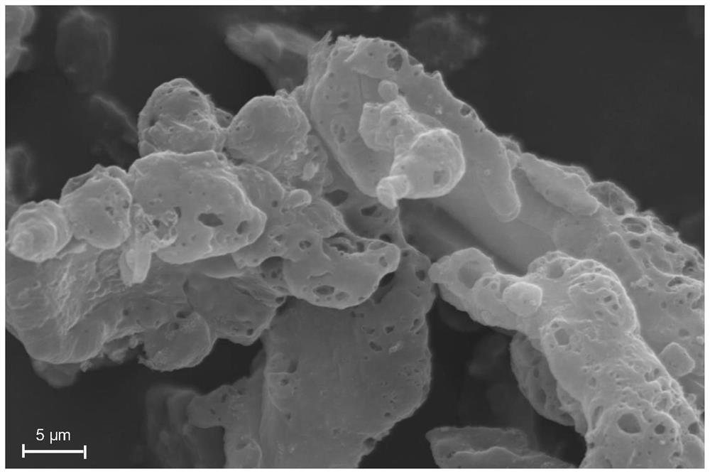
[0035] Weigh 0.5-1.0g of 5-nitroisophthalic acid and 4,4'-bipyridyl into 40-50mL of DMF solution, then add 0.05-1.2g of Zn(NO 3 ) 2 .6H 2 O, Ni(NO 3 ) 2 .6H 2 O and Fe(NO 3 ) 3 .9H 2 O. Then react under an inert atmosphere at a temperature of 100-130° C. for 20-30 hours, cool to room temperature, filter, and dry in a vacuum oven. Finally, the dried sample was raised to 800-1000°C at a heating rate of 5°C / min in a tube furnace, kept at a constant temperature for 30 minutes, and then cooled to room temperature to obtain a sample FeNi@NCF. The X-ray diffraction pattern of the product is shown in figure 1 ; Scanning Electron Microscopy, see figure 2 ; transmission electron microscope image see image 3 ; Nitrogen adsorption curve and pore size distribution diagram are shown in Figure 4 .

Embodiment 2

[0036] Example 2 Electrocatalytic OER performance test of FeNi@NCF

[0037] The electrocatalytic OER performance test of FeNi@NCF obtained in Example 1 was performed on a CHI760E electrochemical workstation at room temperature using a classic three-electrode system for electrochemical testing. The electrolyte is 1.0M KOH solution. Hg / HgO and Pt sheets were used as reference and counter electrodes. Take 2mg FeNi@NCF, add 150uL ultrapure water, 150uL isopropanol and 25uL Nafion177, and after ultrasonic for 1 hour, drop the sample on the glassy carbon electrode as the working electrode. Figure 5 The linear sweep voltammetry curve shown is obtained at a scan rate of 5mV / s. It can be seen from the figure that FeNi@NCF drives 10mAcm on the glassy carbon electrode -2 The required overpotential for the current density is 270mV, respectively. Image 6 The Tafel plot shown is from Figure 5 It is calculated that the Tafel slope of FeNi@NCF on the glassy carbon electrode is 67mV dec...

Embodiment 3

[0038] Example 3 FeNi@NCF electrochemical specific surface area test

[0039] To determine the electrochemical surface area (ECSA), cyclic voltammetry (CV) measurements were used to explore the electrochemical double layer capacitance (C dl ). CV is performed in the non-Faraday range (1.10-1.20Vvs RHE) with sweep rates of 20, 60, 100, 140 and 180mV s -1. A linearity plot was obtained by plotting the current density versus scan rate at 1.15 Vvs RHE. C dl is half the slope of the linear graph and is used to represent ECSA. The electrochemical specific surface area diagram is shown in Figure 8 .


PUM


Abstract

The invention discloses a method for preparing a foamy carbon supported FeNi alloy catalyst by utilizing a nitro-modified metal organic framework (MOFs) and application of the foamy carbon supported FeNi alloy catalyst in the field of energy catalysis. The preparation method comprises the following steps: synthesizing MOFs (Metal-Organic Frameworks) modified by nitryl and containing metals Fe and Ni by utilizing a ligand containing nitryl through a one-pot method, drying in vacuum, and pyrolyzing in an inert atmosphere to obtain a foamy carbon loaded FeNi nano-alloy material (FeNi-NCF). The FeNi-coated NCF structure is porous and bulky, the loaded metal nanoparticles are uniformly distributed, the average particle size is 11nm, and the specific surface area is higher than 500m < 2 >/g. The catalyst is simple in preparation method and low in cost, has high potential industrial application value in the field of energy catalysis, and can be used for electro-catalytic water decomposition, oxygen reduction reaction, carbon dioxide reduction reaction and various organic catalytic reactions.

Description

technical field [0001] The invention relates to the field of preparation of FeNi alloy nanomaterials and energy catalysis, in particular to the synthesis of a nitro-modified metal-organic framework to prepare a foamed carbon-supported FeNi alloy catalyst and its application as an electrocatalytic water splitting catalyst. Background technique [0002] MOFs are a class of porous crystalline materials that are interconnected by metal ions or metal clusters and organic ligands. By pyrolyzing MOFs under suitable atmosphere and temperature, they can be transformed into porous carbon-based supported metal nanoparticles or metal oxide materials. Carbon-based nanomaterials derived from MOFs have the characteristics of high specific surface area, high porosity, high conductivity, high stability, corrosion resistance, and adjustable structure and function, and have become one of the research hotspots in the field of heterogeneous catalysis. In addition, because the unique channels of...

Claims


Application Information

Patent Timeline
IPC IPC(8): C25B11/091C25B1/02C25B3/25C25B3/26C25B3/23
Inventor 何纯挺章佳刘娟丽曹黎明
Owner JIANGXI NORMAL UNIVERSITY
Why Eureka
Try Eureka