Process of maximizing production of chemical raw materials by gaseous phase catalytic cracking crude oil with multi-stages in milliseconds in combination with hydrogenation

a gaseous phase catalytic cracking and crude oil technology, applied in the field of maximizing can solve the problems of low yield and selectivity of three olefins, the relative deficiency of light weight cracking raw materials, and the rapid growth of the worldwide market demand for low-carbon olefins, so as to reduce the influence of heat and mass transfer, maximize the production of chemical raw materials, and improve the yield and selectivity of thr

Active Publication Date: 2019-12-17
CHINA UNIV OF PETROLEUM (EAST CHINA)
View PDF11 Cites 0 Cited by
  • Summary
  • Abstract
  • Description
  • Claims
  • Application Information

AI Technical Summary

Benefits of technology

[0008]In order to overcome the shortcomings of the existing technology of processing crude oil with “chemical products dominated pattern”, an object of the invention is to develop a process of maximizing production of chemical raw materials by gaseous phase catalytic cracking crude oil with multi-stages in milliseconds in combination with hydrogenation, which may significantly improve the yield and selectivity of three olefins and three aromatic hydrocarbons, overcome the “cage effect” of the liquid phase reaction, reduce an influence of heat and mass transfer on catalytic cracking, and drastically decrease the amount of generated coke and energy consumption in the cracking process, and maximize utilization of the crude oil resources.
[0009]The process adopted by the invention utilizes millisecond pyrolysis of crude oil in the downflow pipe to maximize production of the oil and gas, this high temperature oil and gas is used for preparing low carbon olefins by directly subjecting to high temperature millisecond shape selective catalytic cracking instead of subjecting to the condensation and separation, and the diesel fraction, recycle oil and oil slurry produced by the shape selective catalytic cracking are subject to hydrogenation for saturation and open-ring and then reused as the raw materials with the crude oil, thereby fully utilizing heat of the pyrolysis oil and gas, significantly improving the yield and selectivity of three olefins and three aromatic hydrocarbons, overcoming the “cage effect” of the liquid phase reaction, reducing an influence of heat and mass transfer on catalytic cracking, and greatly decreasing the amount of generated coke and energy consumption in the cracking process, consequently achieving maximization of the crude oil resources and the high-yield and efficient production of the basic chemical raw materials.
[0023]In the present invention, the term “carrier / oil ratio” refers to the weight ratio of the used amount of solid heat carrier to the used amount of crude oil. When the numerical value of the “carrier / oil ratio” is less than 1, it may likely result in that the heat supply is insufficient, the reaction temperature is excessively low, and the crude oil cannot be completely converted into high temperature oil and gas in gaseous phase, which affects the overall yields of three olefins and three aromatic hydrocarbons of the device. While the numerical value of the “carrier / oil ratio” is greater than 14, it may easily cause that the heat supply is excessive, the crude oil is excessively cracked, the amount of generated coke is increased, the pyrolysis dry gas is increased, and the olefin selectivity of the subsequent reaction is deteriorated.
[0036]In the present invention, the diesel fraction is mixed with the recycle oil and the oil slurry and then the mixture is subject to catalytic saturation and open-ring reaction with hydrogenation catalyst in the hydrogenation reactor, its effect resides in converting the polycyclic aromatic hydrocarbons included in this mixture, which are difficult to be cracked and may be easily coked, into paraffins which can be easily cracked; that is, if the mixture is directly mixed with crude oil for pyrolysis without performing saturation or open-ring reaction, it may cause a lowered yield of three olefins, an increased amount of generated coke, thereby affecting the economic benefit of the apparatus.
[0039]The invention provides a process of maximizing production of chemical raw materials by gaseous phase catalytic cracking crude oil with multi-stages in milliseconds in combination with hydrogenation, the process utilizes a rapid alkaline catalytic pyrolysis of the inferior crude oil to maximize production of the oil and gas, this high temperature oil and gas is used for preparing low carbon olefins by directly subjecting to high temperature millisecond shape selective catalytic cracking instead of subjecting to the condensation and separation, thereby fully utilizing heat of the pyrolysis oil and gas, overcoming the “cage effect” of the liquid phase reaction, reducing an influence of heat and mass transfer on catalytic cracking, and significantly decreasing the amount of generated coke and energy consumption in the cracking process; the reaction temperature and time may be easily adjusted and controlled, and the characteristic that the alkaline catalytic pyrolysis of crude oil produces a large amount of olefins may be used for shape selective catalysis, thereby significantly increasing the yield and selectivity of low carbon olefins. For example, the process has a total yield of three olefins (i.e., “ethylene, propylene and butane”) up to 50% for inferior heavy oil having a residual carbon content of 15%, wherein the yields of propylene and ethylene are 28% and 15%, respectively; the total yield of three olefins is much higher than about 35% of the total yield of three olefins from pyrolysis and catalytic cracking of wax oil; the process avoids the reheating, temperature rise and pulverization of the wax oil in the traditional combined process of pyrolysis modification—wax oil catalytic cracking, but it still has a common problem, namely the “cage effect” of the liquid phase reaction results in an increased condensation polymerization, thereby reducing the yield and selectivity of low carbon olefins. In addition, the process has a short processing procedure, the steel consumption of the apparatus is low, the fixed investment is greatly reduced; the atmospheric pressure operation is simple, it is convenient to start or shut down the apparatus, the operational continuity is desirable, and the apparatus has strong adaptability for processing a variety of oils.
[0040]Moreover, as compared with the direct refining of the diesel fraction, recycle oil and the oil slurry as the raw material to be pyrolyzed, the present invention defines that the diesel fraction, the recycle oil and the oil slurry are subject to hydrogenation for saturation, and returns along with the gasoline fraction and are used as the raw materials such that the yield of three olefins (i.e., “ethylene, propylene and butane”) is increased by 3-10 percentage point.

Problems solved by technology

However, in view of the gradual depletion of conventional crude oil resources since the 21st century, the crude oil supply in the world has presented the development trends of heavy weight and inferior quality, leading to a relative deficiency of light weight cracking raw materials, while the worldwide market demand for low-carbon olefins is growing rapidly.
In order to alleviate the imbalance between the supply and demand, broaden the raw materials for producing the low-carbon olefins, and make better use of heavy feedstock oil, the development of “chemical products dominated pattern” technical routes that use heavy oil as a raw material to directly produce low-carbon olefins through catalytic cracking process has become the focus and hotspot of research in the petroleum refining industry at home and abroad, however, there are very few mature technologies that can be industrialized.
However, the active components of the shape selective catalyst for heavy oil catalytic cracking are mainly ZSM-5 and Y-type molecular sieves, whose pore structures have a small size, so the diffusion of large heavy oil molecules are limited during the mass transfer process, and it is difficult for the large heavy oil molecules to enter into the molecular sieves to conduct a shape-selective cracking; moreover, the acidic molecular sieves have a strong hydrogen transfer performance, which leads to a limited increase in the yield and selectivity of the olefins.
In addition, the heavy oil macromolecules accumulated on the surface of molecular sieves are prone to overcracking under the action of the acid site, resulting in poor product distribution or coking and condensation, thereby blocking the pore channels of catalyst.
At present, the existing industrial shape selective catalysts are used to prepare low-carbon olefins through catalytic cracking of the inferior materials such as atmospheric pressure residue oil, vacuum residue oil, deasphalted oil, which often leads to many problems such as catalyst poisoning, poor atomization effect, large amount of generated coke, and significantly lowered conversion rate and selectivity.

Method used


Image

  • Process of maximizing production of chemical raw materials by gaseous phase catalytic cracking crude oil with multi-stages in milliseconds in combination with hydrogenation

Examples


example 1

[0090]The crude oil treated in the example is the thickened oil from the Shengli Oil Field in China with a residual carbon content of 15%. The key property parameters are shown in Table 1:

[0091]

TABLE 1Density (kg / m3, 20° C.)1,012.8Viscosity (mm · s−1, 100° C.)471Residual carbon content15.0(wt. %)Carbon content (wt. %)85.6Hydrogen content (wt. %)7.4

[0092]The solid heat carrier is a calcium aluminate porous microspheres having a particle size ranging from 15 to 150 micrometers.

[0093]The cracking catalyst is ZSM-5 molecular sieve with a particle size ranging from 15 to 150 microns.

[0094]The hydrogenation catalyst is a composite of a nickel-based hydrogenation catalyst and a molecular sieve catalyst with a mass ratio of 2:1.

[0095]The process flow is as follows:

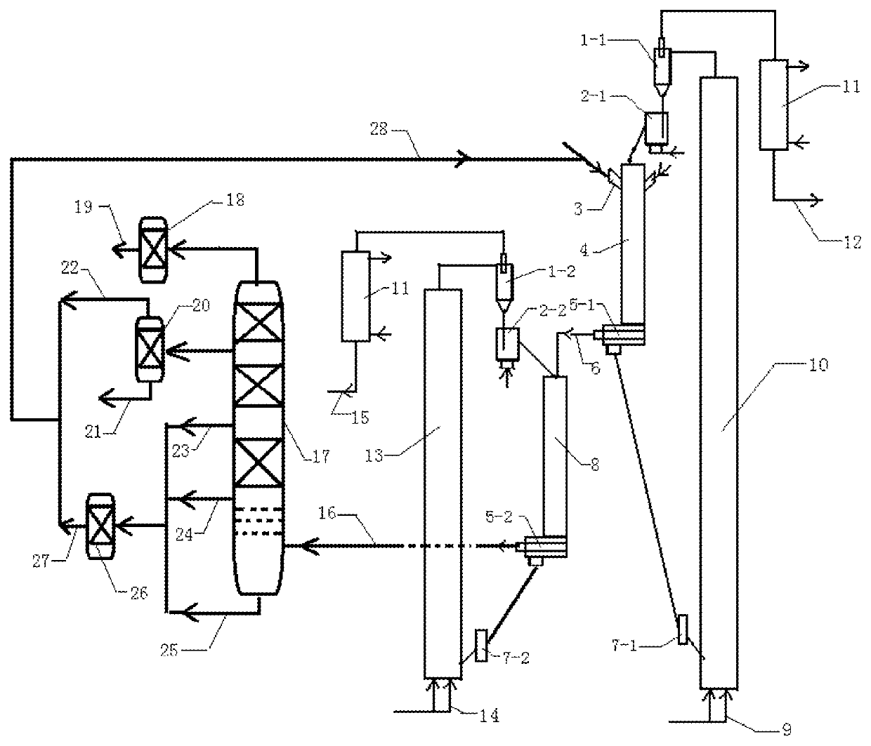
[0096]1) the thickened oil from the Shengli Oil Field preheated to 180° C. is sprayed from a feed inlet of a downflow modification reaction tube into an upper portion of the downflow modification reaction tube, the produced oil mi...

example 2

[0124]The crude oil treated in the example is the thin oil from the Shengli Oil Field. The key property parameters are shown in Table 2:

[0125]

TABLE 2Density (kg / m3, 20° C.)834.1Viscosity (mm · s−1, 100° C.)56Residual carbon content (wt. %)3.2Carbon content (wt. %)82.6Hydrogen content (wt. %)9.1

[0126]The solid heat carrier is aluminum silicate porous microsphere having a particle size ranging from 15 to 150 micrometers.

[0127]The cracking catalyst is ZSM-5 molecular sieve having a particle size ranging from 15 to 150 microns.

[0128]The hydrogenation catalyst is identical with that in Example 1.

[0129]The process flow is as follows:

[0130]1) the thin oil from the Shengli Oil Field preheated to 150° C. is sprayed from a feed inlet of a downflow modification reaction tube into an upper portion of the downflow modification reaction tube, the produced oil mist is mixed with a high temperature solid heat carrier (aluminum silicate porous microspheres) at a temperature 1,000° C. flowing downwar...

example 3

[0144]The crude oil processed in the example is identical with that in Example 1.

[0145]The solid heat carrier is the porous microsphere carrier loaded with alkali metal (Na), the porous microsphere carrier has a particle size ranging from 15 to 150 micrometers.

[0146]The cracking catalyst is a FCC molecular sieve catalyst having a particle size ranging from 15 to 150 micrometers.

[0147]The hydrogenation catalyst is identical with that in Example 1.

[0148]The process flow is as follows:

[0149]1) the thickened oil from the Shengli Oil Field preheated to 300° C. is sprayed from a feed inlet of a downflow modification reaction tube into an upper portion of the downflow modification reaction tube 4, the produced oil mist is mixed with a high temperature solid heat carrier (porous microsphere carrier loaded with Na) at a temperature 800° C. flowing downward from the first return controller for milliseconds, so as to heat, vaporize and pyrolyze the heavy oil, the pyrolysis reaction temperature...


PUM

PropertyMeasurementUnit
temperatureaaaaaaaaaa

Abstract

The invention provides a process of maximizing production of chemical raw materials by gaseous phase catalytic cracking crude oil with multi-stages in milliseconds in combination with hydrogenation, comprising: a high-efficiency atomizing nozzle sprays the preheated crude oil into an upper portion of the downflow modification reaction tube, the produced oil mist is mixed with a high temperature heat carrier flowing downward from a first return controller for pyrolysis in milliseconds and then the pyrolysis products are subject to a gas-solid separation; the coked heat carrier obtained by the separation enters into a modification regeneration reactor to conduct a regeneration reaction, the obtained high temperature heat carrier returns to a top of the downflow reaction tube to participate in circulation, the regeneration gas is subject to heat exchange and then output; the high temperature oil and gas produced by the pyrolysis reaction directly flow into the millisecond cracking reactor and conduct a cracking reaction with the regenerated cracking catalyst and subject to a gas-solid separation; then the cracking catalyst to be regenerated enters the crack regeneration reactor and performs a regeneration reaction and then are subject to a gas-solid separation, the obtained high temperature crack catalyst passes through a second return controller and flows into the millisecond cracking reactor to participate the circulation reaction, the obtained flue gas is subject to heat exchange and then output; the cracked oil and gas produced by the cracking reaction enter into a fractionation tower for separation, thereby obtain the cracked gas, gasoline fraction, diesel fraction, recycle oil and oil slurry; furthermore, the diesel fraction, recycle oil and oil slurry are subject to saturation or open-ring in a hydrogenation reactor, return and mix with crude oil such that the mixture is used as a raw material.

Description

CROSS REFERENCE TO RELATED APPLICATIONS[0001]The application claims priority to Chinese Application No. 201810341186.5, filed on Apr. 17, 2018, entitled “Process of Maximizing Production of Chemical Raw Materials by Gaseous Phase Catalytic Cracking Crude Oil with Multi-stages in Milliseconds in Combination with Hydrogenation”, which is specifically and entirely incorporated herein by reference.FIELD OF THE INVENTION[0002]The invention provides a process of maximizing production of chemical raw materials by gaseous phase catalytic cracking crude oil with multi-stages in milliseconds in combination with hydrogenation, it belongs to the technical field of petroleum processing.BACKGROUND OF THE INVENTION[0003]The three olefins (i.e., “ethylene, propylene and butane”) and three aromatic hydrocarbons (i.e., “benzene, toluene, xylene”) are vital basic organic chemical materials, especially the production capability of ethylene is often regarded as a symbol of the development level of petro...

Claims


Application Information

Patent Timeline
Patent Type & Authority Patents(United States)
IPC IPC(8): C10G9/28C10G51/04C10G67/02
CPCC10G67/02C10G2400/20C10G2400/04C10G2300/302C10G2400/02C10G2400/06
Inventor TIAN, YUANYUQIAO, YINGYUNZHANG, JUNTAOZHANG, JINHONGJIANG, YUANLI, JIE
Owner CHINA UNIV OF PETROLEUM (EAST CHINA)
Why Eureka
Try Eureka