
Metal oxide nanofibrous materials for photodegradation of environmental toxins

a technology of metal oxide nanofibers and environmental toxins, applied in the field of photocatalytic materials, can solve the problems of limited photocatalytic activity of pure tiosub>2 /sub>fibers, and achieve the effects of enhanced photodegradation, rapid and inexpensive, and time-consuming

Active Publication Date: 2020-05-26
THE RES FOUND OF STATE UNIV OF NEW YORK
View PDF68 Cites 3 Cited by
  • Summary
  • Abstract
  • Description
  • Claims
  • Application Information

AI Technical Summary

Benefits of technology

[0084]The present technology comprises a composition of one-dimensional nanomaterial electrospun nanofibers. The invention employs the application of photocatalysis and irradiation in the UV or visible region of the spectrum to excite an electron from the valence band (leaving behind a hole) to the conduction band of a semiconductor. These photoinduced charge carriers then proceed to form reactive radicals, e.g., hydroxyl radicals, super oxide, carboxylic acid anion radical, benzyl radical, benzonitrile radical, chalcogenide radical, nitrous oxide radical, sulfoxide radical, etc. that attacks proximate chemicals. Electromagnetic radiation in the form of visible light, ultra-violet light, or even sunlight can be used to achieve enhanced photodegradation that are both rapid and inexpensive compared to the current decomposition techniques that are costly and time consuming. Compared with other photocatalytic materials, one-dimensional nanomaterial electrospun nanofibers have attracted considerable attention due to their high specific surface area to volume ratio, ease of fabrication and functionalization, and versatility in controlling the fiber diameter, morphology, and reactivity. Electrospun nanofibers from stable polymers are ideal candidates for catalytic supports as they can provide a large surface area and a high porosity for catalytic applications. Due to the high surface area to volume ratio, electrospun nanofibers can provide many active anchor sites for doping and bonding with other materials such as graphene and metal-organic frameworks (MOFs).
[0085]Nanotechnology can provide novel systems for rapid decontamination and protection through a self-cleaning mechanism. The basic principle of this self-cleaning system is the application of photocatalysis. Nanofibrous photocatalysts use incident irradiation in the UV or visible region of the spectrum to excite an electron from the valence band (leaving behind a hole) to the conduction band of a semiconductor. These photoinduced charge carriers then proceed to form reactive radicals, hydroxyl radicals and super oxide radicals that attack adsorbed chemicals on the surface of the material. Electromagnetic radiation in the form of visible light, ultra-violet light, or even sunlight can be used to achieve enhanced photodegradation that are both rapid and inexpensive compared to the current decomposition techniques that are costly and time consuming. Metal oxide nanofibrous materials represent an alternative approach to conventional composites used in photocatalytic degradation. Their one dimensional morphology is desired compared to traditional nanoparticles; owing to excellent mobility of charge carriers, high surface area to volume ratio, the existence of pores enhancing charge collection and transport. One-dimensional metal oxide nanofibrous materials have attracted considerable attention due to their high specific surface area, ease of fabrication and functionalization, and versatility in controlling the fiber diameter and morphology.
[0086]Electrospun nanofibers from stable polymers are ideal candidates for catalytic supports as they can provide a large surface area and a high porosity for catalytic applications. In order to develop novel self-cleaning surfaces and substrates for photodegradation of environmental toxins, some fundamental studies have been investigated on the electrospinning technique, calcination temperature influence on TiO2 phase changes and phase transformation rates of pre-calcined polymer fibers with different diameters. Prepared are a variety of electrospun nanofibrous materials such as, anatase TiO2, rutile TiO2, reduced graphene oxide TiO2, BaTiO3, platinum nanoparticles supported on anatase TiO2, ZnO, photoactive dye supported anatase TiO2. These fibers have been characterized by X-Ray diffraction, Scanning Electron Microscopy, Transmittance Electron Microscopy, Raman Microscopy and Energy-Dispersive X-Ray Spectroscopy. Also, electrospun TiO2 nanofibers show excellent UV degradation results on rhodamine B (Rh.B.), phenazopyridine (PAP) and dimethyl methylphosphonate (DMMP). The photocatalytic activity of pure TiO2 fibers is limited by fast electron-hole pairs' recombination and a relative high energy band gap. Some multifunctional TiO2 fibers have been also fabricated to solve these problems. These novel multifunctional materials offer excellent mobility of charge carriers for faster degradation and the possibility to exploit catalytic processes in decontamination.
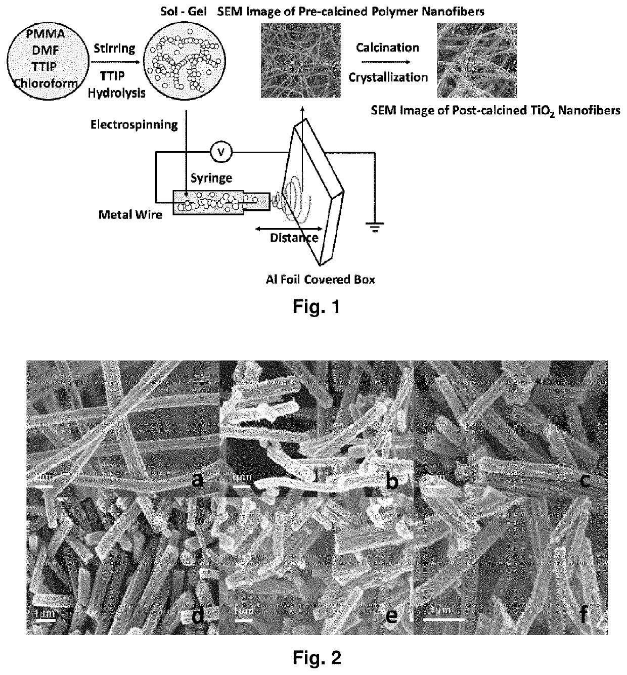
[0087]The preferred fabrication process takes advantage of an electrospinning process, a non-mechanical, electrostatic process that can produce fibers in the nanometer to micrometer range using electrically driven jets of polymer solution or melts. In this process, a high electric field is created between the polymer fluid and an electrically conducting collector screen. At a critical electrical potential which overcomes surface viscosity, a thin jet is produced from the charged polymer fluid at the tip of a pipette or syringe needle. The solvent evaporates rapidly as the jet is drawn through the air to the collector screen where dry fibers accumulate to produce a mat of nanofibers. The obtained polymer fibers are often allowed time to undergo hydrolysis and polycondensation reactions, followed by thermal treatment in order to favor structural stability via sintering, densification, grain growth and phase transformation. Some fundamental studies have been investigated on the electrospinning technique, calcination temperature influence on TiO2 phase changes and phase transformation rates of pre-calcined polymer fibers with different diameters. Some multifunctional TiO2 nanofibers have been also fabricated to improve the photodegradation performance in visible light irradiation. This technology can be used for treatment of polluted waste water, for the improvement of gas masks, for integration with conventional textiles for self-decontaminating garments, and for spray treatments of combat vehicles.
[0100]The nanofibers may be used for breakdown or modification of various chemicals and pollutants. One embodiment provides a gasmask employing a filter comprising the nanofibrous sheet, which is moistened and illuminated with ultraviolet light during use. Volatile organic compounds in the air interact with free radicals generated from oxygen and moisture adsorbed to the nanofibers, which are then broken down. Similarly, a photocatalytic air filter for an HVAC system can also be provided. The nanofibers may also be used within a water processing system to treat / disinfect water, such as tapwater, to degrade pollutants and kill microorganisms. The nanofibers may also used in a system to activate a stream of water, such as for clothes and dishwashing machines, to reduce reliance on chlorine bleach and reduce detergent consumption. The nanofibers may also be used as photoinitiators in processes that require free radical species. Further, the nanofibers may be used in medical applications to provide targeted toxic therapies, such as skin lesions, neoplasia and tumors, and the like, as well as in certain cosmetic procedures. The UV light may come from sunlight, fluorescent / gas discharge lamps, ultraviolet light emitting diodes, or other known sources. In doped or dye linked embodiments, the photoexcitation may be visible or infrared illumination, and for example this is advantageous in medical and cosmetic environments where the ultraviolet illumination is to be avoided. On the other hand, in broadband illumination such as sunlight, one or more photoexcitable dyes may be used to increase efficiency of use of available energy.

Problems solved by technology

The photocatalytic activity of pure TiO2 fibers is limited by fast electron-hole pairs' recombination and a relative high energy band gap.

Method used


Image

  • Metal oxide nanofibrous materials for photodegradation of environmental toxins
  • Metal oxide nanofibrous materials for photodegradation of environmental toxins
  • Metal oxide nanofibrous materials for photodegradation of environmental toxins

Examples


example 1

[0160]Polymethylmethacrylate (PMMA) (Mw 960,000), titanium isopropoxide (TTIP), N,N-dimethylformamide (DMF), chloroform and phenazopyridine hydrochloride (PAP) (Mw 249.70) were all acquired from Sigma Aldrich and used as received.

[0161]1 2 mL of PAP solution with concentration of 144 μM was prepared using DI water as solvent. The solution was transferred into a 16 mL cylindrical quartz container and placed in a fume hood with the lights off. After blanking the UV-Vis Spectrophotometer with DI water in a small quartz cell, an initial reading (marked as T=−60) was taken by diluting 0.5 mL of the PAP solution with 2.0 mL of DI water. Next, 12.0 mg of the catalyst TiO2 nanofibers were added into the 12 mL PAP solution with constant stirring. After 30 and 60 minutes stirring, a 1.0 mL aliquot of the sample was taken and centrifuged for two minutes, which are recoded as sample T=−30 and T=0. Once the sample of T=0 was taken, a UV lamp was turned on at a fixed distance of 9 cm from the cen...

example 2

[0177]Nanotechnology can provide new approaches to the real time decontamination of liquids and solid surfaces. For example, photocatalytic and self-cleaning ability on the hydrophilic surface of TiO2 have found multiple uses in health, environmental and military applications. Specifically, TiO2-based electrospun fibers have great potential for use in chemical and biological decomposition [44], protective / self-cleaning clothing [40, 45], self-cleaning glass [46], and self-cleaning membranes.[47] The basic principle of photocatalytic activity is the use of incident light to excite an electron from the valence band (leaving behind a hole) to the conduction band of a semiconductor. These photoinduced charge carriers then proceed to form reactive radicals, hydroxyl radicals (A−) and super oxide radicals (D+) that attack adsorbed chemicals on the surface of the material, as shown in FIG. 8, which shows a schematic image of the photodegradation process on the surface of TiO2. Previous res...

example 3

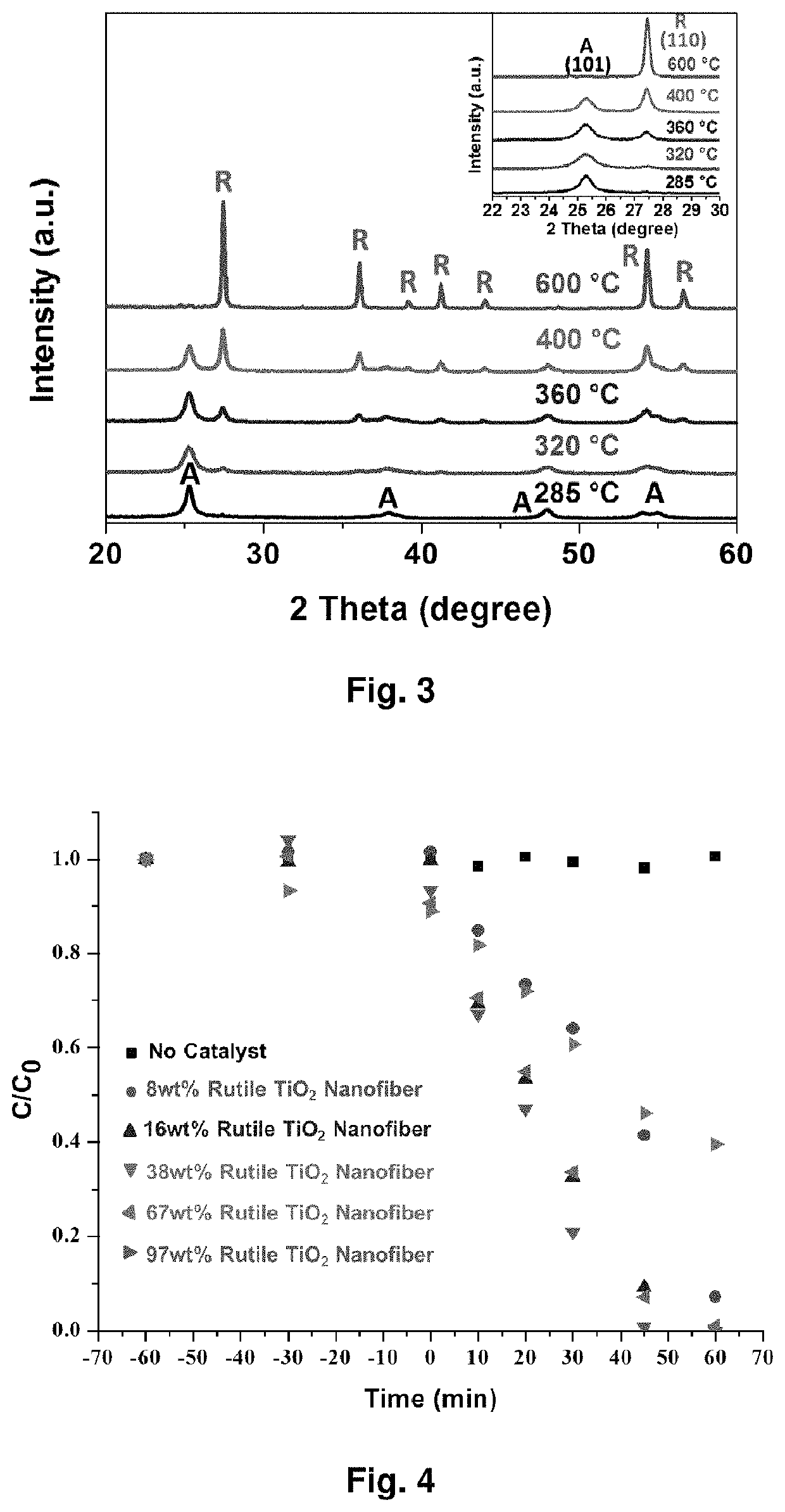
[0185]FIG. 12 shows a schematic representation of the electrospinning process Calcination temperature influence on TiO2 phase changes. Based on the calcination temperatures, TiO2 nanofibers show different phase combination, pure anatase, pure rutile or their mixture. The X-ray diffraction (XRD) in FIG. 13 clearly shows that pure anatase phase of TiO2 shows up at relative lower temperature and it begins to transfer to rutile phase as the temperature increases. The ratios of anatase phase and rutile phase under different temperature are shown in table 1.

[0186]

TABLE 2Polymer nanofibers with different diameters preparedunder different electrospinning parametersDistancePMMA / TIPPMMAbetween Tip toPolymerDiameterPMMA:TTIPMolecularCollectorVoltageFiber(nm)(mg)Weight(cm)(kV)HumidityA638.4 ± 26.3320:640996,000182543%B761.6 ± 40.3320:640996,000112585%C 972.8 ± 134.8320:640996,000112543%

[0187]PMMA / TIP polymer fibers with different diameters can be fabricated by altering the parameters used in so...


PUM

PropertyMeasurementUnit
diameteraaaaaaaaaa
diameteraaaaaaaaaa
distanceaaaaaaaaaa

Abstract

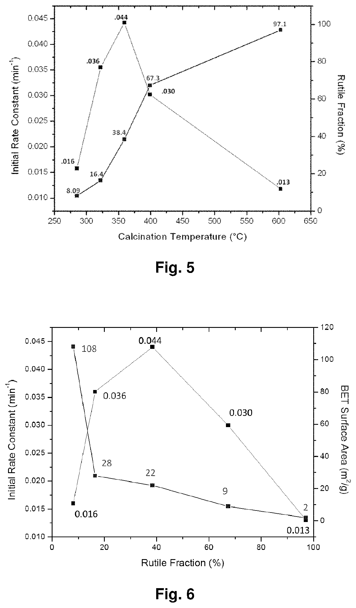
Mixed-phase TiO2 nanofibers prepared via a sol-gel technique followed by electrospinning and calcination are provided as photocatalysts. The calcination temperature is adjusted to control the rutile phase fraction in TiO2 nanofibers relative to the anatase phase. Post-calcined TiO2 nanofibers composed of 38 wt % rutile and 62 wt % anatase exhibited the highest initial rate constant of UV photocatalysis. This can be attributed to the combined influences of the fibers' specific surface areas and their phase compositions.

Description

CROSS REFERENCE TO RELATED APPLICATIONS[0001]This invention is a non-provisional of U.S. Provisional Patent Application No. 62 / 132,611, filed Mar. 13, 2015.GOVERNMENT LICENSE RIGHTS[0002]This invention was made with government support under contract W911NF1310235 awarded by the US Army Research Office. The government has certain rights in the invention.FIELD OF THE INVENTION[0003]The present invention relates to the field of photocatalytic materials, and more particularly to photocatalytic systems and methods for degrading environmental toxins.BACKGROUND OF THE INVENTION[0004]The present invention describes subject matter that relates to nanotechnology systems and methods that provide rapid decontamination and protection.[0005]Huge amounts of environmental toxins, such as toxic industrial chemicals (TICs), toxic organic dyes, bio-pharmaceuticals, and chemical warfare agents (CWAs), bio-accumulate causing chronic and aesthetic pollution to the surrounding environments and human being...

Claims


Application Information

Patent Timeline
Patent Type & Authority Patents(United States)
IPC IPC(8): B01J31/38D01D5/00C04B35/622B01J23/42C04B35/624C04B35/626B01J23/06B01J35/10C04B35/628B01J21/06B01J31/16B01J35/00B01J37/08C02F1/32C02F1/72B01J37/03B01J35/06
CPCD01D5/003B01J35/1014C04B35/62675C02F1/32B01J35/004B01J37/086C04B35/62844B01J21/063C02F1/725B01J31/1691B01J35/1019B01J23/42C04B35/62259B01J31/38C04B35/624B01J23/06B01J37/082B01J35/0013C02F2305/10B01J35/06Y02W10/37C04B2235/5264B01J37/036C04B2235/85C02F2305/08C04B2235/5409
Inventor JONES, WAYNE E.LIU, JIANBERNIER, WILLIAM E.TOLLIN, JULIA B.MCCARTHY, DANIELLEOBUYA, EMILLYDECOSTE, JARED
Owner THE RES FOUND OF STATE UNIV OF NEW YORK
Learn More