Laser ablation process and apparatus

a laser ablation and process technology, applied in the field of laser ablation process and apparatus, can solve the problems of insufficient flow, inability to visualize or treat the flow of the device, and limited information about tissue diagnosis, so as to reduce fresnel reflection, reduce high-unwanted heat transfer, and maximize the effect of transmitted ligh

Inactive Publication Date: 2002-04-18
KITTRELL CARTER +2
View PDF0 Cites 397 Cited by
  • Summary
  • Abstract
  • Description
  • Claims
  • Application Information

AI Technical Summary

Benefits of technology

0021] The protective optical shield mechanically displaces the blood and also protects the fiber(s) from the intra-arterial contents. The fiber(s) are anchored so that there is an appropriate distance between the output end of the fiber(s) and the tip of the shield. The catheter and shield are sealed watertight, preventing blood from coming into contact with the internal components. The intervening space may be filled with fluid, or optical surfaces may be optically contacted, or they may be anti-reflection coated to reduce Fresnel reflec

Problems solved by technology

A partial blockage which causes inadequate flow cannot be visualized or treated by the device.
In addition, the cavity formed by the recess would tend to trap fluid, such as blood, absorbing the laser radiation and hindering it from reaching the target tissue.
Being a visual device, the information which can be provided for diagnosis by the endoscope is limited to what can be seen.
Therefore, the Bass instrument is clearly an instrument not intended for use, and cannot be used, in the vascular system.
Since it is a visual device, the information about the tissue diagnosis is limited to what can be seen.
Also, because visualization is used, the path from the distal end of the instrument to the tissue must be clear, but no means of purging non-transparent fluids (such as blood) is provided.
The difficulty of maneuvering the long flexible catheter to a new spot for each small piece of tissue removed, and the likely damage to the delicate vessel wall from repeated and prolonged manipulation of the device would make its use impractical in such a situation.
Finally, since the control of the laser power is connected to the position of the hand operated attenuating filter, such control is essentially manual, and is therefore orders of magnitude slower than an electronic control system.
It is inadequate for use in a blood vessel where laser radiation can perforate the wall in less than a second.

Method used


Image

  • Laser ablation process and apparatus
  • Laser ablation process and apparatus
  • Laser ablation process and apparatus

Examples


Embodiment Construction

[0059] Components

[0060] Laser Catheter, Preferred Embodiment

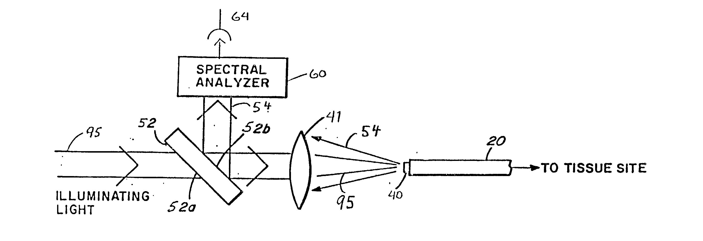
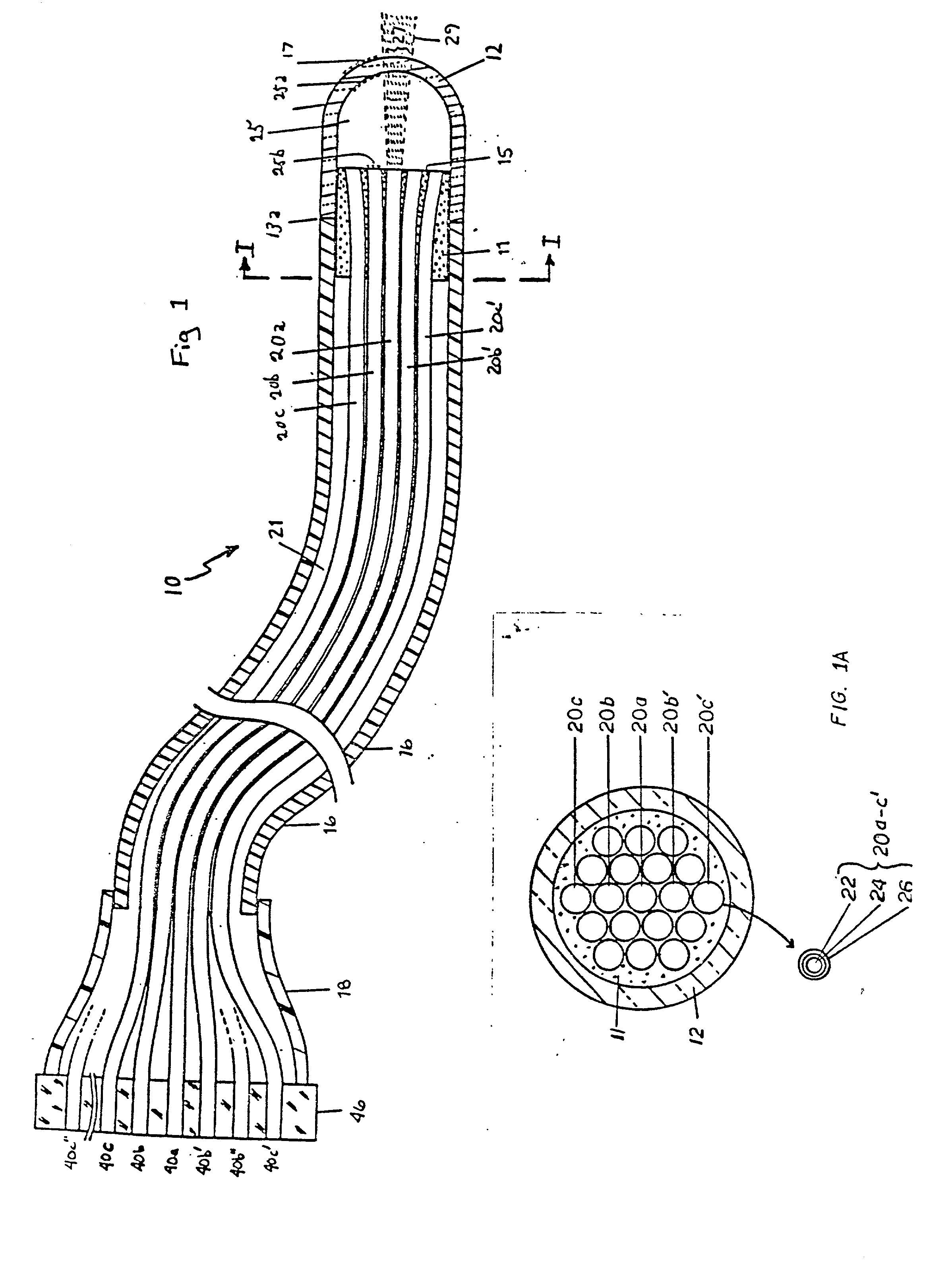
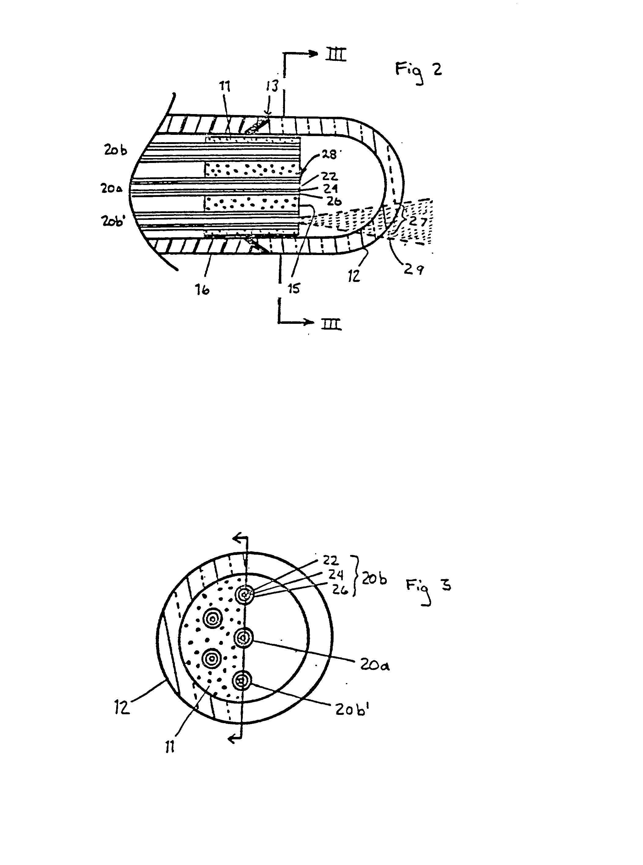
[0061] FIG. 1 shows the preferred embodiment of the entire laser catheter 10 in broken longitudinal section. It is terminated at the distal end by the optical shield 12 and at the proximal end by the fiber optic coupler 46. The flexible catheter body 16, with lumen 21, is typically 1 / 2 to 2 meters long and is designed for insertion into or in contact with the patient. A protective enclosure 18 which connects the catheter body 16 to the coupler 46 is preferably short but may be of any length. The optical shield 12 is a transparent enclosure made of fused silica, glass, or sapphire or other optically transparent material capable of withstanding heat, steam and high laser power. Optical transparency may include ultraviolet, visible and infrared light, depending on the light and laser sources used.

[0062] The distal end of optical shield 12 of FIG. 1 is shown with a hemispherical cross section, but it may also be rectangular, fl...


PUM

PropertyMeasurementUnit
Timeaaaaaaaaaa
Angleaaaaaaaaaa
Poweraaaaaaaaaa

Abstract

A laser catheter is disclosed wherein optical fibers carrying laser light are mounted in a catheter for insertion into an artery to provide controlled delivery of a laser beam for percutaneous intravascular laser treatment of atherosclerotic disease. A transparent protective shield is provided at the distal end of the catheter for mechanically diplacing intravascular blood and protecting the fibers from the intravascular contents, as well as protecting the patient in the event of failure of the fiber optics. Multiple optical fibers allow the selection of tissue that is to be removed. A computer controlled system automatically aligns fibers with the laser and controls exposure time. Spectroscopic diagnostics determine what tissue is to be removed.

Description

[0001] The term "laser" is an acronym for Light Amplification by Stimulated Emission of Radiation. As used herein, the term is meant to encompass a device which utilizes the principle of amplification of electromagnetic waves by stimulated emission of radiation to produce coherent radiation in the infrared, visible or ultraviolet region. Such radiation has been used in external medical applications, such as for cauterizing, for attaching detached retinas and for removing various skin cancers.[0002] Likewise, optical fibers have been used in a variety of medical applications. An optical fiber is a clad plastic or glass tube wherein the cladding is of a lower index of refraction than the core of the tube. When a plurality of such tubes are combined, a fiber optic bundle is produced. Optical fibers are flexible and are therefore capable of guiding light in a curved path defined by the placement of the fiber.[0003] Fiber optic scopes have been developed for medical technology in order t...

Claims


Application Information

Patent Timeline
IPC IPC(8): A61B5/00A61B18/20A61B18/22A61B18/24B23K26/03B23K26/067G02B6/04G02B6/14G02B6/24G02B6/35G02B6/42
CPCA61B1/00096G02B6/4296A61B5/0075A61B5/0084A61B18/20A61B18/245A61B2018/00636A61B2018/2238G01N2021/4747G02B6/04G02B6/14G02B6/241G02B6/3504G02B6/3508G02B6/3512G02B6/3516G02B6/3548G02B6/3598A61B5/0071
Inventor KITTRELL, CARTERCOTHREN, ROBERT M. JR.FELD, MICHAEL S.
Owner KITTRELL CARTER
Why Eureka
Try Eureka