Thermal spray particles and sprayed components

a technology of sprayed components and spray particles, which is applied in the direction of lanthanide oxides/hydroxides, cellulosic plastic layered products, natural mineral layered products, etc., can solve the problems of large repose angle, poor fluidity, and difficulty in producing particle-free dense components, and achieves better adhesion and corrosion resistance, high density and strength

Inactive Publication Date: 2002-11-28
SHIN ETSU CHEM IND CO LTD
View PDF0 Cites 45 Cited by
  • Summary
  • Abstract
  • Description
  • Claims
  • Application Information

AI Technical Summary

Benefits of technology

0012] The invention addresses rare earth-containing compound particles for thermal spraying. We have found that by controlling the average particle diameter, dispersion index and aspect ratio to specific ranges, conforming the particle shape to a polyhedron, and optionally, controlling the surface area, bulk density, crystallite size and impurity content to specific ranges,

Problems solved by technology

Although components using alumina, silica or the like have been developed as the sprayed component, it is difficult to produce particle-free dense components.
However, the fused or sintered and ground powder resulting from method (1) or (2), though having sufficient strength, has irregular shapes and a broad particle size distribution so that the friction between particles during transportation entails formation of finer particles.
Additionally, the powder has a large angle of repose and poor fluidity so that the transportation tube or spray gun can be clogged, preventing continuous thermal spraying operation.
Particles with a low strength will readily collapse during the feed to the spray gun.
As the process to make the granulated powder is complicated and composed of number of steps, it becomes difficult to prevent introduction of impurities such as Fe.
In the event where granulated powder is prepared using a spray drying granulator, however, an average particle diameter o

Method used


Image

  • Thermal spray particles and sprayed components
  • Thermal spray particles and sprayed components
  • Thermal spray particles and sprayed components

Examples


example 1

[0041] Oxalic acid (H.sub.2C.sub.2O.sub.4.2H.sub.2O), 794.3 g, was dissolved in 9.27 dm.sup.3 of deionized water, to which 900 cm.sup.3 of 28% aqueous ammonia was added. With stirring, the solution was heated at 75.degree. C.

[0042] Separately, 4.29 dm.sup.3 of a mixed solution of ytterbium nitrate and yttrium nitrate (Yb concentration 0.28 mol / dm.sup.3, Y concentration 0.42 mol / dm.sup.3, free acid concentration 1.40 mol / dm.sup.3) was prepared at room temperature. With stirring, this solution was poured to the oxalic acid solution, which had been prepared and heated above, over about one minute. The solution mixture was further stirred for 2 hrs while keeping at a temperature of 72 to 75.degree. C.

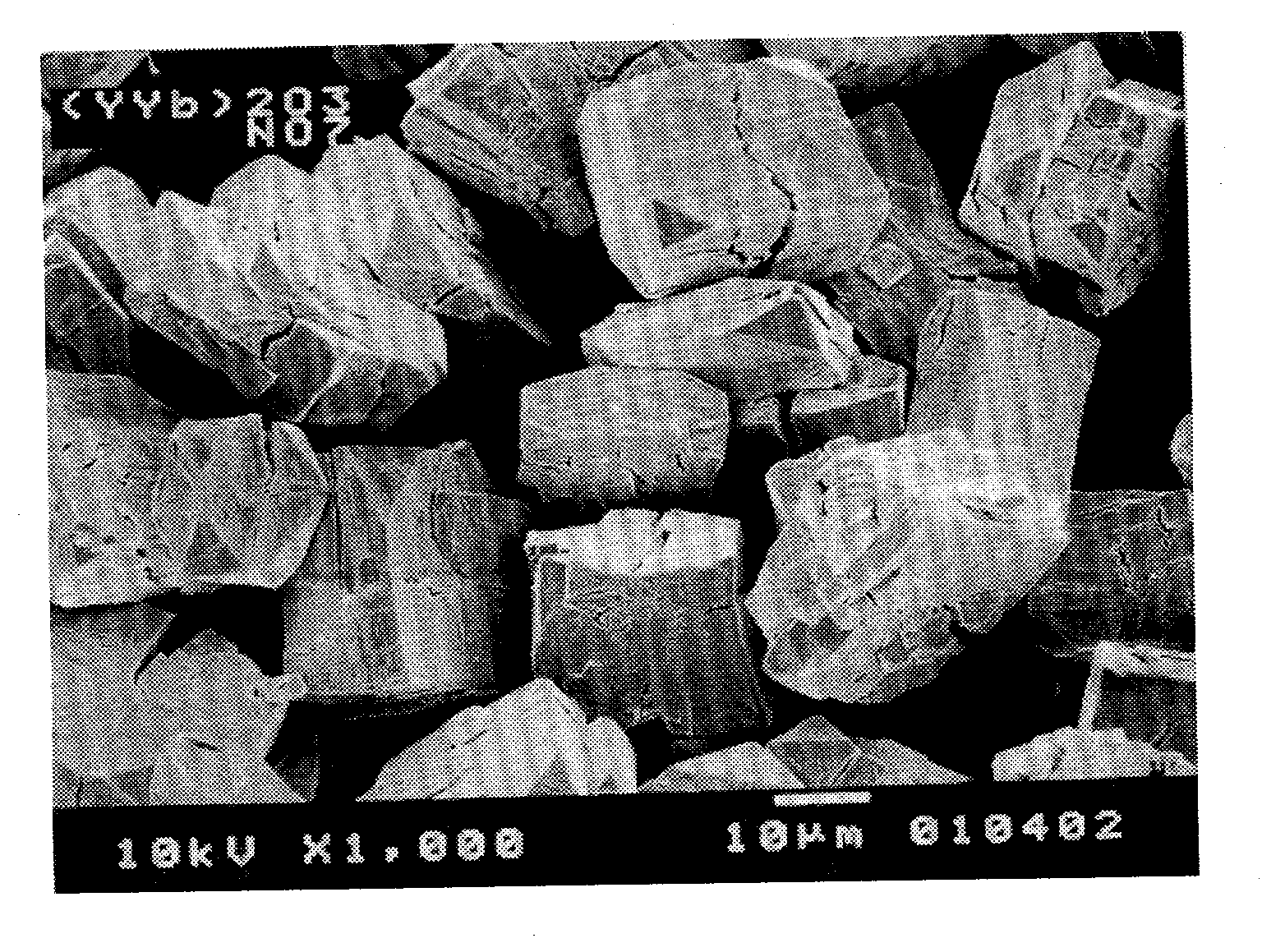
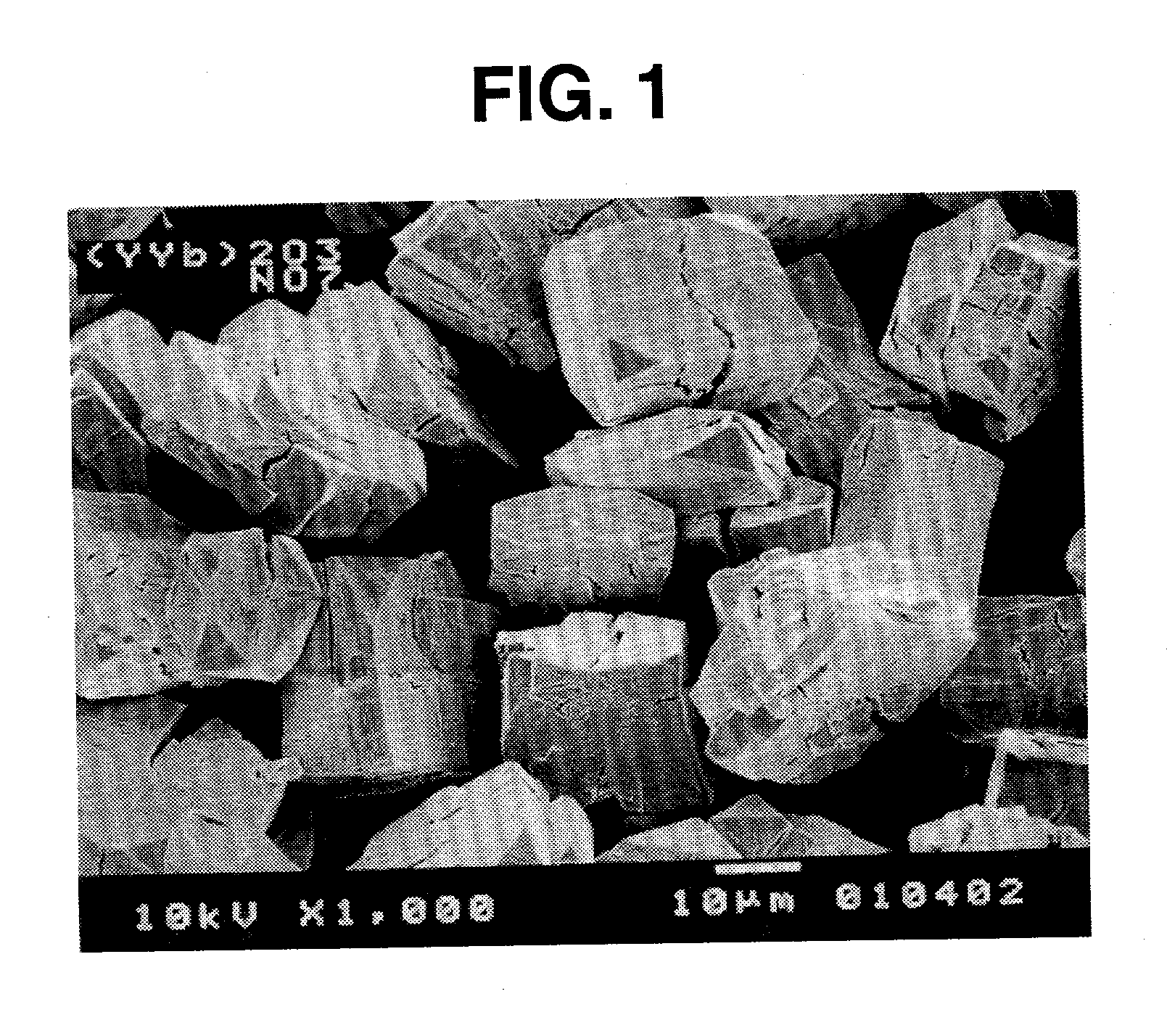
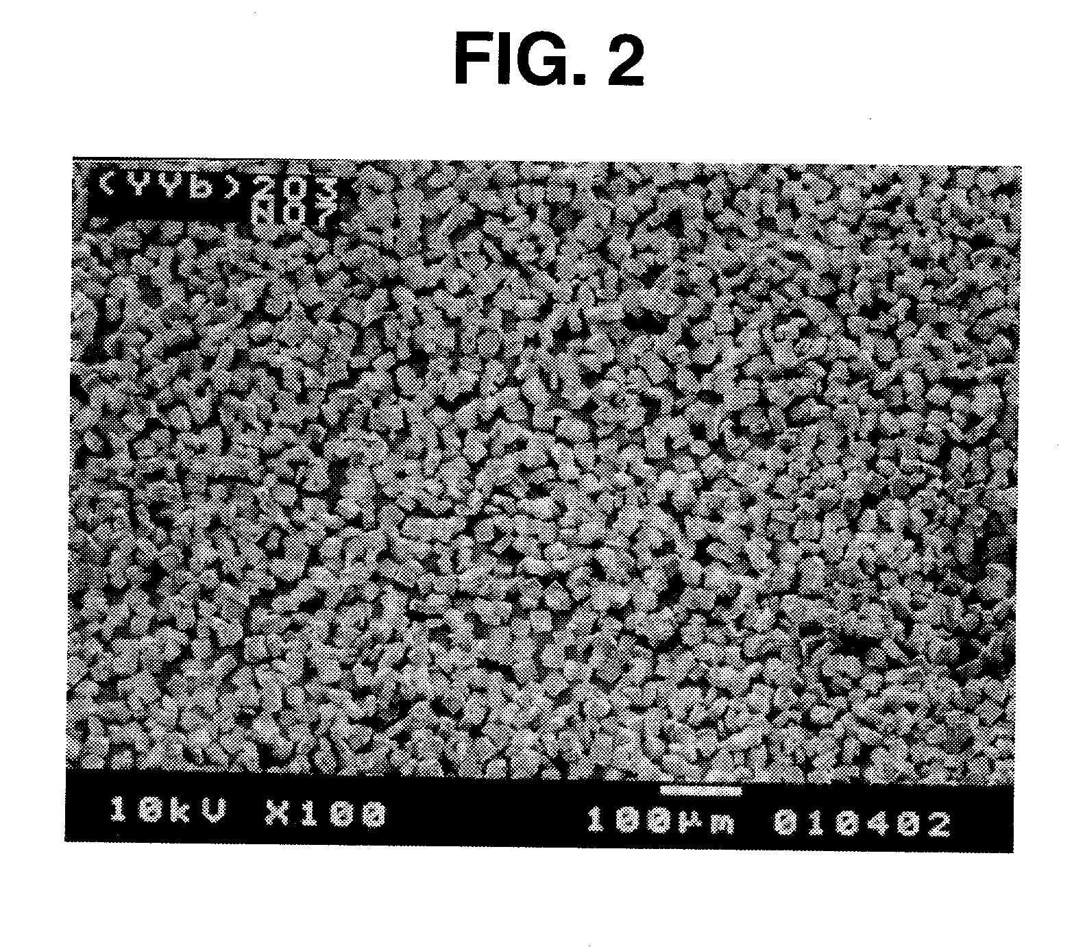
[0043] Thereafter, the precipitate formed was collected on a Buchner funnel and washed with 15 dM3 of deionized water. The precipitate thus collected was air dried for 2 hours. The precipitate or oxalate was placed in a porcelain crucible and fired in air at 900.degree. C. for 2 hours, wher...

example 2

[0046] Particles for thermal spraying were prepared as in Example 1 except that a ytterbium nitrate solution (Yb concentration 0.70 mol / dm.sup.3, free acid concentration 1.40 mol / dm.sup.3) was used instead of the mixed solution of ytterbium nitrate and yttrium nitrate. The particles were measured for physical properties including particle diameter and crystallite size, with the results shown in Table 1.

[0047] Using an argon / hydrogen gas plasma, the particles were sprayed to an aluminum alloy substrate to form a coating of 210 .mu.m thick thereon. The coating was examined for surface roughness and impurity content, with the results shown in Table 2.

[0048] Like Example 1, the particles obtained in Example 2 had an angular shape (regular polyhedral shape), though photomicrograph is omitted.


PUM

PropertyMeasurementUnit
Fractionaaaaaaaaaa
Lengthaaaaaaaaaa
Sizeaaaaaaaaaa

Abstract

Rare earth-containing compound particles of polyhedral shape having an average particle diameter of 3-100 .mu.m, a dispersion index of up to 0.5, and an aspect ratio of up to 2 can be thermally sprayed to form an adherent coating, despite the high melting point of the rare earth-containing compound. A sprayed component having the particles spray coated on a substrate surface is also provided.

Description

[0001] This invention relates to rare earth-containing compound particles for thermal spraying, and a sprayed component. More particularly, it relates to rare earth-containing compound particles which can be plasma or otherwise sprayed to surfaces of metal or ceramic substrates to form highly adherent, smooth and highly pure coatings, and a sprayed component having a coating of the rare earth-containing compound particles.BACKGROUND OF THE INVENTION[0002] It is a common practice in the art to thermally spray metal oxide particles to metal, ceramic and other substrates to form a coating thereof for imparting heat resistance, abrasion resistance and corrosion resistance.[0003] The particle powders suitable for thermal spray coatings typically include (1) a fused and ground powder obtained by melting a starting material in an electric furnace, cooling the melt for solidification, and pulverizing the solid in a grinding machine into particles, followed by classification for particle siz...

Claims


Application Information

Patent Timeline
IPC IPC(8): C01F17/218C01F17/224C04B35/50C04B35/505C23C4/04C23C4/08C23C4/10
CPCC01F17/0043Y10T428/256C01P2004/01C01P2004/22C01P2004/30C01P2004/52C01P2004/54C01P2004/61C01P2006/10C01P2006/12C01P2006/21C01P2006/22C04B35/50C04B35/505C23C4/04C23C4/08C23C4/10C23C4/105Y10T428/2982C01P2002/60C23C4/11C01F17/218C01F17/224
Inventor KANEYOSHI, MASAMIMAEDA, TAKAO
Owner SHIN ETSU CHEM IND CO LTD
Why Eureka
Try Eureka