Porous silicon nitride ceramics and method for producing the same

a technology ceramics, which is applied in the field of porous silicon nitride ceramics and the field of production of the same, can solve the problems of difficult to obtain, uneven characteristics, and weak strength, and achieve excellent electrical/mechanical characteristics and reduce the effect of dielectric loss

Inactive Publication Date: 2004-01-22
SUMITOMO ELECTRIC IND LTD
View PDF3 Cites 7 Cited by
  • Summary
  • Abstract
  • Description
  • Claims
  • Application Information

AI Technical Summary

Benefits of technology

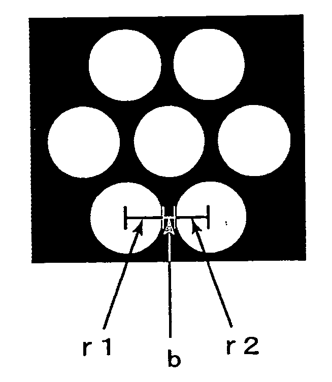
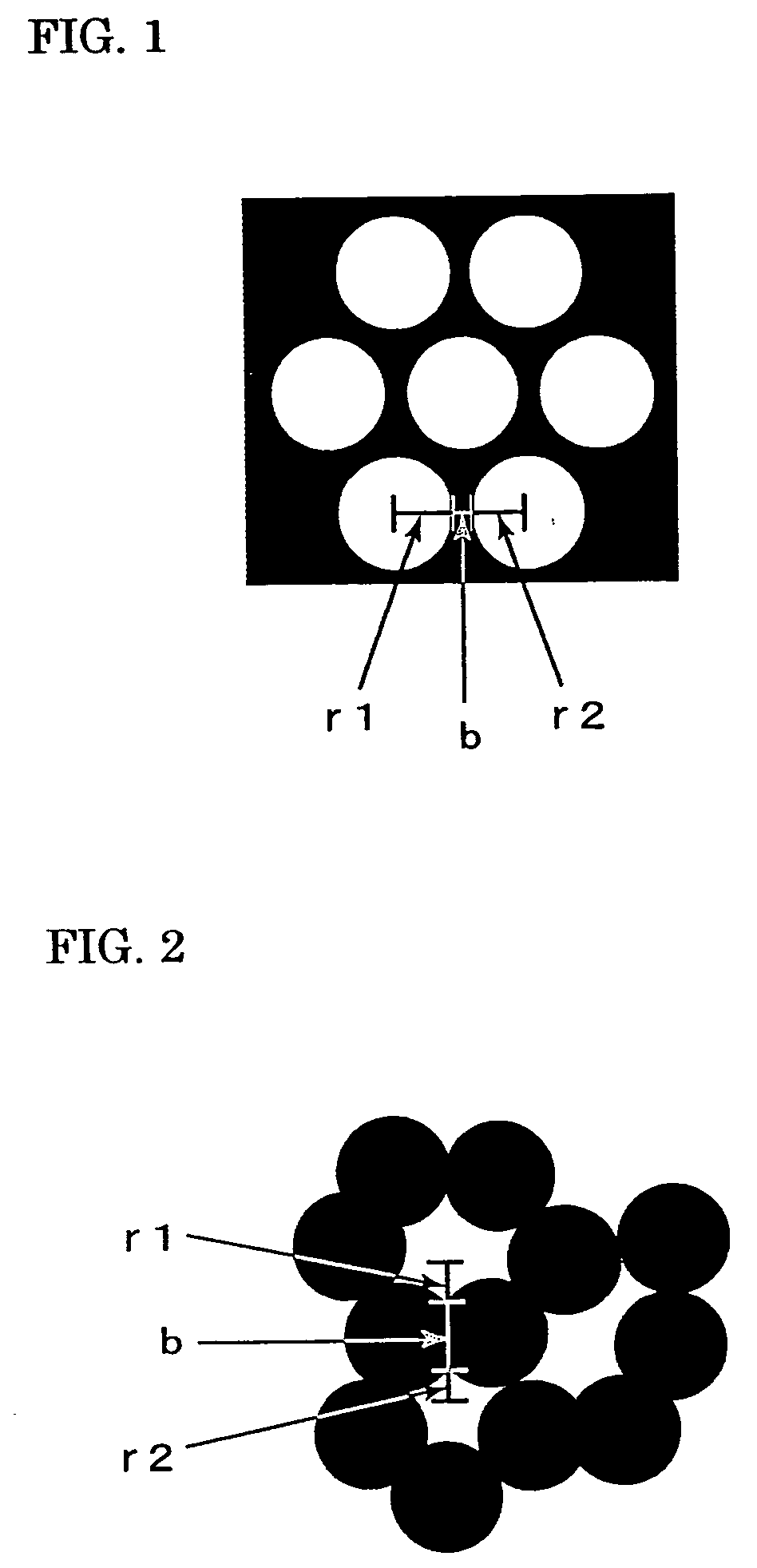
0034] In an arbitrary section of the porous silicon nitride ceramics of the present invention, if the radii of adjoining pores are represented as r1 and r2, respectively, and the thickness of a ceramic part is represented as b, as shown in FIG. 1, the relation (r1+r2) / b>1 is established. In other words, the diameter of a pore can be made equal to or greater than the thickness of the ceramic part by selecting the average particle diameter, and oxygen content at the surface, of raw material metal Si powder, the kind of sintering additive, and the sintering conditions. Preferably, (r1+r2) / b>2. This structure makes it possible to further reduce the dielectric loss.
0035] A preferable embodiment of the porous silicon nitride ceramics of the present invention has a dielectric loss of about 10.sup.-4 or less. As for a mechanical characteristic, the deflective strength by three-point bending is 200 MPa or more, and the porous silicon nitride ceramics are excellent in electrical / mechanical characteristics.

Problems solved by technology

However, it is difficult to obtain, merely by controlling a sintering process of the ceramic sintered body, a porous sintered body in which fine pores are uniformly dispersed.
Normally, a situation occurs in which its strength is weakened or its characteristics become uneven because of the generation of coarse pores.
In addition, there has been a problem in the fact that, since most pores of a resulting porous sintered body are open pores, moisture resistance inherent in ceramics is impaired, and a marked deterioration in electrical characteristics (permittivity and dielectric loss) caused by water or unevenness in various characteristics occurs and, as a result, desired characteristics cannot be practically obtained.
However, a problem with this technique is that oxidation resistance will decrease, or a pore diameter will increase if an attempt is made to obtain an SiC-based porous sintered body that has 27.5% or more closed pores.
However, a problem with this method is that the closed porosity cannot be heightened because residues of the foaming agent or the combustible fine powder exist in closed pores, and the increase in the foaming agent makes it difficult to maintain its shape.
However, a problem in this method is that it is difficult to control the pore diameter and difficult to obtain high porosity.
However, according to this method, although the grainy resin is sublimed and burned so as to form closed pores, the grainy resin remains in the ceramics, or the combustion gas of the grainy resin is adsorbed to the inner surface of the dosed pores, thereby decreasing its electrical characteristics.
Another problem in this method is the fact that it is difficult to form a complete closed pore even if it is an independent pore in appearance, and an additional contrivance is needed to obtain airtightness.
Additionally, not only is the process complicated, but also materials need to be used while being complexed into different phases, and therefore the inherent mechanical, electrical characteristics cannot be obtained.
Still another problem in this method is that, once open pores are exposed to the atmosphere and water is adsorbed, it is difficult to completely dissociate and control this.
As described above, the conventional methods for forming closed pores require an addition of a second phase different from a matrix phase, such as a foaming agent, melting substance, or a phase different in the thermal expansion coefficient, and therefore, electrical / mechanical characteristics greatly and disadvantageously decrease because of the second phase or because of the residues of the second phase.
Additionally, since the heightening of porosity makes it impossible to form a matrix frame or impossible to control the pore diameter, there is a limit to the porosity and the pore diameter that can be formed.

Method used


Image

  • Porous silicon nitride ceramics and method for producing the same
  • Porous silicon nitride ceramics and method for producing the same
  • Porous silicon nitride ceramics and method for producing the same

Examples


example 2

[0043] Si powder having the average particle diameter of 1 .mu.m and, as sintering additives in the amount of 0.8 mol % with respect to the Si powder, rare-earth oxides as listed in Table II each having the average particle diameter of 0.8 .mu.m were prepared. Each powder is commercially available. The Si-powder, whose oxygen content at the surface was pre-confirmed to be 0.7 mol % in terms of SiO.sub.2, by measuring according to an inert-gas fusion and infrared detection method, was prepared. Each powder thus prepared was subjected to mixing, molding, and thermal treatment in the same way as in Example 1.

[0044] Thereafter, the atmosphere was changed to a nitrogen atmosphere of the atmospheric pressure. The temperature was then raised to 1000.degree. C., and held for three hours, and then raised to 1200.degree. C., and held for three hours. After natural cooling, finish machining was performed in the same way as in Example 1. The whole porosity, closed porosity, permittivity, and di...

example 3

[0047] Si powder having the average particle diameter of 1 .mu.m and, as sintering additives at the ratios shown in Table III with respect to the Si powder, Yb.sub.2O.sub.3 each having the average particle diameter of 0.8 .mu.m were prepared. Each powder is commercially available. The Si-powder, whose oxygen content at the surface was pre-confirmed to be 0.7 mol % in terms of SiO.sub.2 by measuring in the same manner as in Example 1, was prepared. Mixing, molding, sintering, and finishing were performed in the same manner as in Example 2. The whole porosity, closed-pore percentage, and dielectric loss of the obtained sintered bodies were measured in the same manner as in Example 1, and the results are shown in Table III.

3TABLE III Amount of addition Whole porosity Closed-pore No. (mol %) (%) percentage (%) tan .delta. (.times.10.sup.-5) 15* 0.16 65 30 100 16 0.78 67 98 9 17 2.5 50 85 20 18* 6 42 45 220 *comparative example

[0048] From Table III, it is understood that, if the amount o...

example 4

[0049] Si powders whose average particle diameter was 0.8 to 10 .mu.m and, as a sintering additive, Sm.sub.2O.sub.3 having average particle diameter of 0.8 .mu.m in the amount of 0.8 mol % with respect to the Si powder, were prepared. The oxygen content of each Si-powder at the surface was measured according to the method recited in Example 1, and the results (in terms of SiO.sub.2) are shown in Table IV. Each powder is commercially available. Mixing, molding, sintering, and finishing were performed in the same manner as in Example 2 with these powders. In the sample of No. 22, an oxidation inhibitor was not added while ball-mill mixing was being performed. The whole porosity and closed-pore percentage of each sintered body were measured in the same manner as in Example 1, and the results are shown in Table IV. Grain boundary phases identified by X-ray diffraction are also shown in Table IV.

4TABLE IV Surface Particle oxygen Whole Closed-pore Grain diameter content porosity percentag...


PUM

PropertyMeasurementUnit
porosityaaaaaaaaaa
pore diameteraaaaaaaaaa
dielectric constantaaaaaaaaaa

Abstract

The invention provides porous silicon nitride ceramics that have uniform, fine closed pores and a manufacturing method thereof. Metal Si powder is mixed with a sintering additive, followed by thermal treatment, which is a pre-process for forming a specific grain boundary phase. Two-stage thermal treatment is thereafter performed by microwave heating at a temperature of 1000° C. or more. The metal Si powder is thereafter subjected to a nitriding reaction from its surface, the metal Si is thereafter diffused to nitride formed on the outer shell of the metal Si, and thereby porous silicon nitride ceramics that have uniform, fine closed pores can be obtained. Since the porous silicon nitride ceramics of the present invention have a high ratio of closed pores and are superior in electrical/mechanical characteristics, excellent characteristics can be displayed if they are used, for example, for an electronic circuit board that requires an anti-hygroscopicity, a low dielectric constant, a low dielectric loss, and mechanical strength.

Description

[0001] This invention relates to porous silicon nitride ceramics used as dielectric materials, which are used for various wiring circuit boards, insulating members, or radio-wave transmission materials, or used as lightweight, anti-hygroscopic structural materials, and relates to a manufacturing method thereof.[0002] Ceramics are materials used as various structural materials and electronic-parts materials, and, in recent years, demands have been made to improve its characteristics, i.e., to further reduce the weight, to increase the strength, and to upgrade the electrical characteristics. For example, in a wafer transporting stage and a drawing stage that are each used as a semiconductor manufacturing device component, stage materials are required to further reduce their weights for high accuracy and high-speed driving. Additionally, a circuit board and insulating material that are used for electronic equipment strongly require materials that are smaller in permittivity and in diel...

Claims


Application Information

Patent Timeline
Patent Type & Authority Applications(United States)
IPC IPC(8): C04B35/584C04B35/591C04B38/00H05K1/03
CPCC04B2111/00198Y10T428/24917Y10T428/24926H05K1/0306C04B2235/96C04B2235/85C04B2235/80C04B2235/77C04B2235/667C04B2235/483C04B2235/465C04B2235/46C04B2235/428C04B2235/3895C04B2235/3873C04B35/591C04B35/6261C04B35/62625C04B35/63C04B35/64C04B38/0025Y10T428/252C04B2235/3217C04B2235/3224C04B2235/3227C04B2235/3272C04B2235/3852C04B35/584C04B38/0061C04B38/0074C04B40/0014C04B35/597C04B38/0054Y10T428/249967Y10T428/249976Y10T428/249971Y10T428/249974Y10T428/249956Y10T428/249953C04B38/00
Inventor MIYANAGA, MICHIMASAKOMURA, OSAMU
Owner SUMITOMO ELECTRIC IND LTD
Why Eureka
Try Eureka