Acoustic matching layer, ultrasonic transmitter/receiver, and ultrasonic flowmeter

Inactive Publication Date: 2004-07-01
PANASONIC CORP
View PDF14 Cites 25 Cited by
  • Summary
  • Abstract
  • Description
  • Claims
  • Application Information

AI Technical Summary

Benefits of technology

0101] Also, if the acoustic matching layer is made of an inorganic oxide, then water should be absorbed and moisture resistance might be a problem. Accordingly, the inorganic oxide skeleton is preferably hydrophobized (or water repellent). In that case, even if water or impurities exist in the gas under measurement, the acoustic matching layer would not be affected by their absorption or deposition so easily. As a result, a more reliable acoustic matching layer can be obtained.
0102] The inorganic oxide skeleton may be hydrophobized with a surface treating agent such as a silane coupling agent. Examples of preferred surface treating agents include: halogen silane treating agents such as trimethylchlorosilane, dimethyldichlorosilane, methyltrichlorosilane and ethyltrichlorosilane; alkoxy silane treating agents such as trimethylmethoxy silane, trimethylethoxysilane, dimethyldimethoxysilane and methyltriethoxysilane; silicone silane treating agents such as hexamethyldisiloxane and dimethylsiloxane oligomer; amine silane treating agents such as hexamethyldisilazane; and alcohol treating agents such as propyl alcohol, butyl alcohol, hexyl alcohol, octanol and decanol.
0103] Also, if a fluorination treating agent, obtained by substituting fluorine for part or all of hydrogen of the alkyl group included in any of these treating agents, is used, then not only hydrophobization (water repellency) but also oil repellency and soil resistance are achieved effectively.
0105] FIG. 2 schematically illustrates a cross-sectional structure of a piezoelectric vibrator 8 for use in an ultrasonic transducer according to an embodiment of the present invention. The piezoelectric vibrator 8 is used in an ultrasonic transducer for an ultrasonic flowmeter.
0106] The piezoelectric vibrator 8 for converting electricity into ultrasonic waves, or vice versa, includes a piezoelectric layer 4 and the acoustic matching layer 1 of the first embodiment described above. The piezoelectric layer 4 generates ultrasonic vibrations, is made of a piezoceramic or piezoelectri

Problems solved by technology

Also, in such an ultrasonic flowmeter, if the alternating current voltage is applied to one of the ultrasonic transducers continuously, then the ultrasonic transducer radiates an ultrasonic wave continuously, thereby making it difficult to measure the propagation time.
However, if an ultrasonic wave is transmitted o

Method used


Image

  • Acoustic matching layer, ultrasonic transmitter/receiver, and ultrasonic flowmeter
  • Acoustic matching layer, ultrasonic transmitter/receiver, and ultrasonic flowmeter
  • Acoustic matching layer, ultrasonic transmitter/receiver, and ultrasonic flowmeter

Examples


example 1

[0166] An ultrasonic transducer according to the present invention was fabricated in the following manner:

(a) Making a Second Acoustic Matching Layer of Glass Epoxy

[0167] A jig was filled with glass balloons, which were impregnated with an epoxy solution and then thermally cured at 120.degree. C. Thereafter, this cured and molded body was cut such that the thickness thereof was equal to a quarter of the oscillation wavelength of the ultrasonic wave.

[0168] The resultant second acoustic matching layer had a sonic velocity of 2,500 m / s, a density of 500 kg / m.sup.3 and a thickness of 1.25 mm with respect to an ultrasonic wave at about 500 kHz.

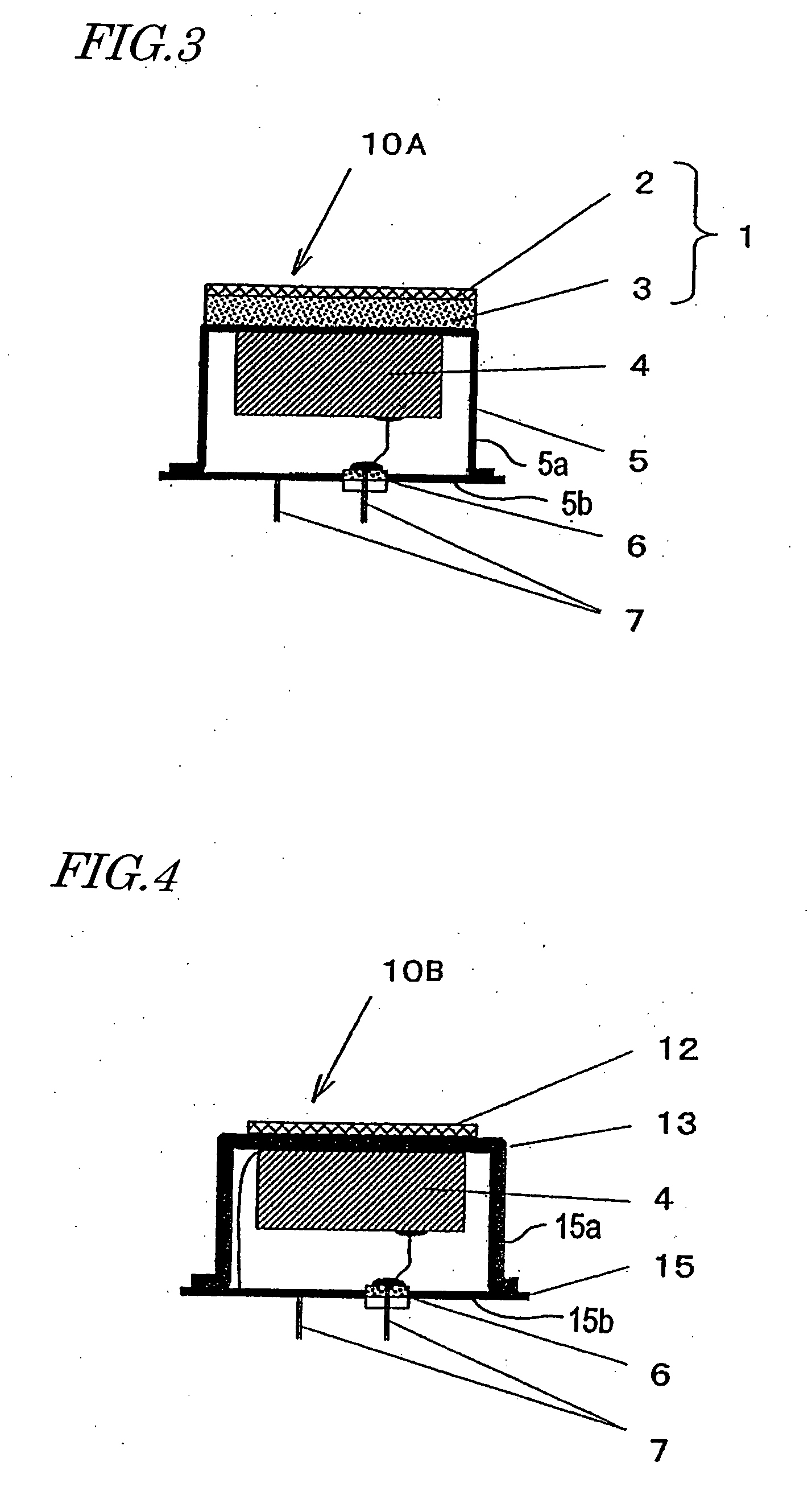
(b) Bonding the Second Acoustic Matching Layer and a Piezoelectric Body onto a Case

[0169] An adhesive was printed on both sides of the top plate of a case, on one surface of a piezoelectric layer, and on one surface of the second acoustic matching layer. In such a state, the piezoelectric body and second acoustic matching layer are attached to the ...

example 2

[0173] Another ultrasonic transducer according to the present invention was fabricated in the following manner:

(a) Making a Second Acoustic Matching Layer of a Silica Porous Body

[0174] A spherical acrylic resin with a diameter of several tens of .mu.m and a sintered silica powder with a size of 1 .mu.m or less were mixed together and then the mixture was pressed and compacted. The resultant compact was dried and then baked at 900.degree. C., thereby obtaining a silica porous body. Thereafter, its thickness was adjusted so as to be equal to a quarter of the oscillation wavelength of the ultrasonic wave.

[0175] The resultant second acoustic matching layer had a sonic velocity of 1,500 m / s, a density of 570 kg / m.sup.3 and a thickness of 750 .mu.m with respect to an ultrasonic wave at about 500 kHz.

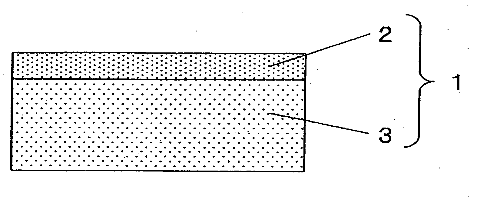
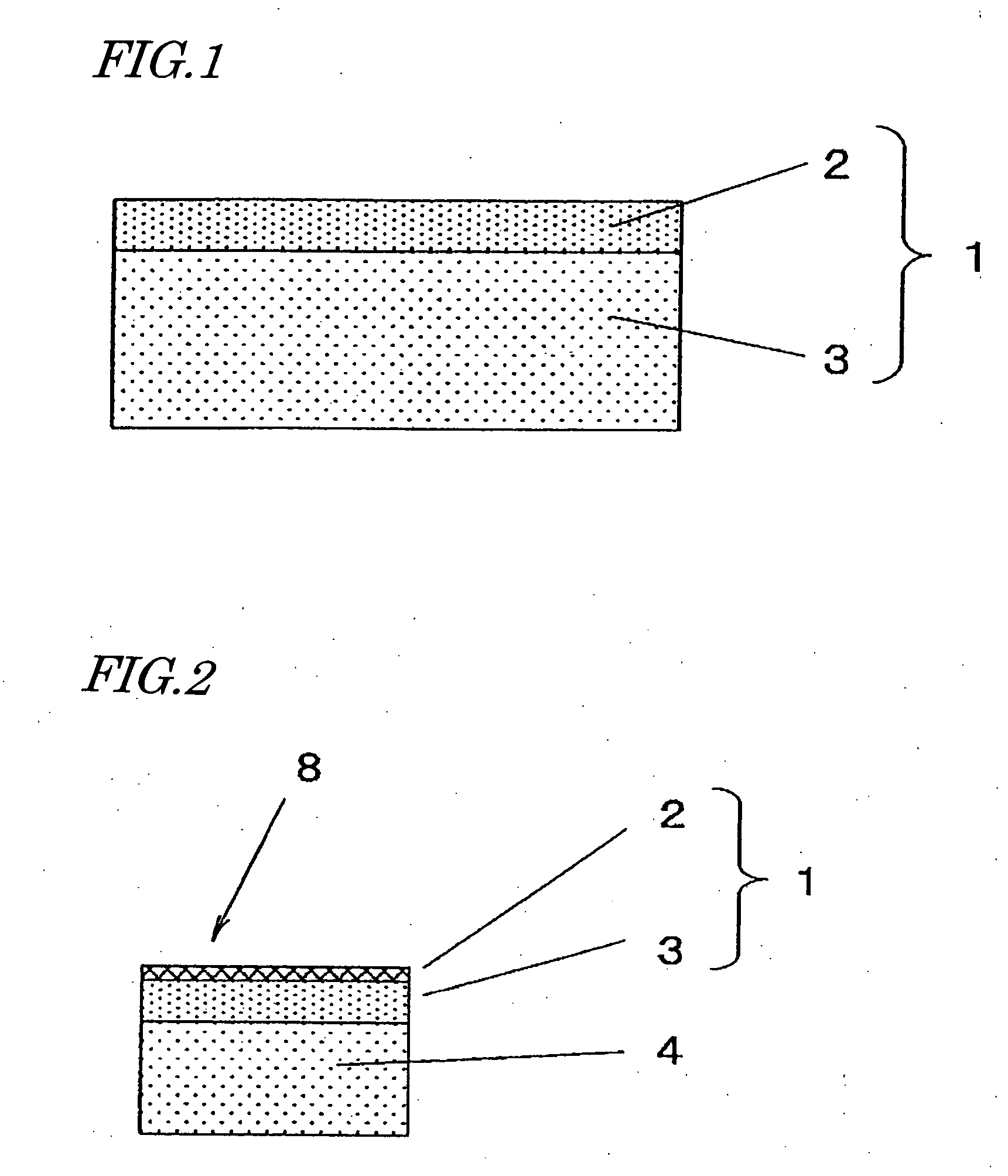
(b) Stacking a First Acoustic Matching Layer on the Second Acoustic Matching Layer

[0176] A gel material solution was prepared by mixing tetramethoxysilane, ethanol and ammonia water (with a no...

example 3

[0182] Still another ultrasonic transducer according to the present invention was fabricated in the following manner:

(a) Making a Second Acoustic Matching Layer of a Silica Porous Body

[0183] A sintered silica powder with particle sizes of several .mu.m to several tens of .mu.m was compacted. The resultant compact was baked at 900.degree. C., thereby obtaining a silica porous body with a thickness that was approximately equal to a quarter of the oscillation wavelength of the ultrasonic wave. The resultant second acoustic matching layer of this silica porous body had a sonic velocity of about 4,000 m / s, a density of about 1,200 kg / m.sup.3 and a thickness of about 2 mm with respect to the ultrasonic wave at about 500 kHz.

[0184] Next, a glass layer with a thickness of 3 .mu.m (and a density of about 3,000 kg / m.sup.3) was provided as a structure supporting layer on one surface of this second acoustic matching layer of the silica porous body. This glass layer had a sonic velocity of about...


PUM


Abstract

An acoustic matching layer 1 according to the present invention includes a first acoustic matching layer 2, which has a low density and a low sonic velocity, and a second acoustic matching layer 3, which has a higher density and a higher sonic velocity. The first acoustic matching layer 2, of which the acoustic impedance is matched to that of a medium into an ultrasonic wave is radiated, is provided closer to the medium, while the second acoustic matching layer 3 is provided closer to a piezoelectric layer, thereby increasing the sensitivity of an ultrasonic transducer.

Description

[0001] The present invention relates to an acoustic matching layer for use in an ultrasonic sensor, an ultrasonic transducer to transmit or receive an ultrasonic wave, a method for fabricating such an ultrasonic transducer, and an ultrasonic flowmeter using such an ultrasonic transducer.[0002] In recent years, an ultrasonic flowmeter has been used as a gas meter, for example. The ultrasonic flowmeter measures the time that it takes for an ultrasonic wave to go through a propagation path and calculates the flow velocity of a fluid, thereby obtaining its flow rate.[0003] FIG. 12 shows a measuring principle of such an ultrasonic flowmeter. As shown in FIG. 12, a fluid is flowing through a tube at a velocity V in the indicated direction. A pair of ultrasonic transducers 101 and 102 is provided on the tube wall 103 so as to face each other. Each of the ultrasonic transducers 101 and 102 includes a piezoelectric body, made of a piezoceramic, for example, as an electromechanical energy con...

Claims


Application Information

Patent Timeline
IPC IPC(8): G01F1/66G10K11/02
CPCG10K11/02G01F1/662G01F1/66
Inventor SUZUKI, MASAAKIHASHIDA, TAKASHIHASHIMOTO, KAZUHIKOHASHIMOTO, MASAHIKONAGAHARA, HIDETOMOSHIRAISHI, SEIGOTAKAHARA, NORIHISA
Owner PANASONIC CORP
Why Eureka
Try Eureka