Oxidation resistant ferritic stainless steels

a technology oxidation resistance, which is applied in the direction of final product manufacturing, solid-state diffusion coating, fuel cell details, etc., can solve the problems of low electrical conductivity of surface oxide layer, difficult fabrication, and brittle lacrosub>3/sub>ceramic, and achieve improved oxidation resistance, improved oxidation resistance of ferritic stainless steel, and reduced surface roughness

Inactive Publication Date: 2005-03-03
ATI PROPERTIES
View PDF15 Cites 25 Cited by
  • Summary
  • Abstract
  • Description
  • Claims
  • Application Information

AI Technical Summary

Benefits of technology

The present disclosure is further directed to a method for making a ferritic stainless steel article having an oxidation resistant surface, and wherein the steel includes aluminum, at least one rare earth metal and 16 to less than 30 weight percent chromium, the total weight of rare earth metals being greater than 0.02 weight percent. The oxidation resistant surface of the ferritic stainless steel is provided by electrochemically modifying the surface, such as, for example, by electropolishing the surface. In one embodiment of the method, the electrochemically modified surface develops an aluminum-rich oxide scale including iron and chromium and having a hematite structure, ao in the range of 4.95 to 5.04 Å and co in the range of 13.58 to 13.75 Å, when heated in an oxidizing atmosphere for 100 hours or more at a temperature in the range of 750° C. (1382° F.) to 850° C. (1562° C.). Also, in certain embodiments of the method, the article is one of a plate, a sheet, a strip, a foil, a bar, a fuel cell interconnect, a high-temperature manufacturing apparatus, a high-temperature handling apparatus, a calcining apparatus, a glass making apparatus, a glass handling apparatus, and a heat exchanger component. An example of electropolishing a surface of the ferritic stainless steel includ

Problems solved by technology

LaCrO3 ceramic, however, is brittle, difficult to fabricate, and extremely expensive.
Metallic interconnects, however, generally tend to form a surface oxide layer with low electrical conductivity at the high temperatures typical of PSOFC operation.
However, the underlying mechanism that controls these two seemingly disparate factors (resistivity and rate of oxide formation) is essentially the same (the electronic defect structure of the oxide), resulting in very few oxides

Method used


Image

  • Oxidation resistant ferritic stainless steels
  • Oxidation resistant ferritic stainless steels
  • Oxidation resistant ferritic stainless steels

Examples


example 1

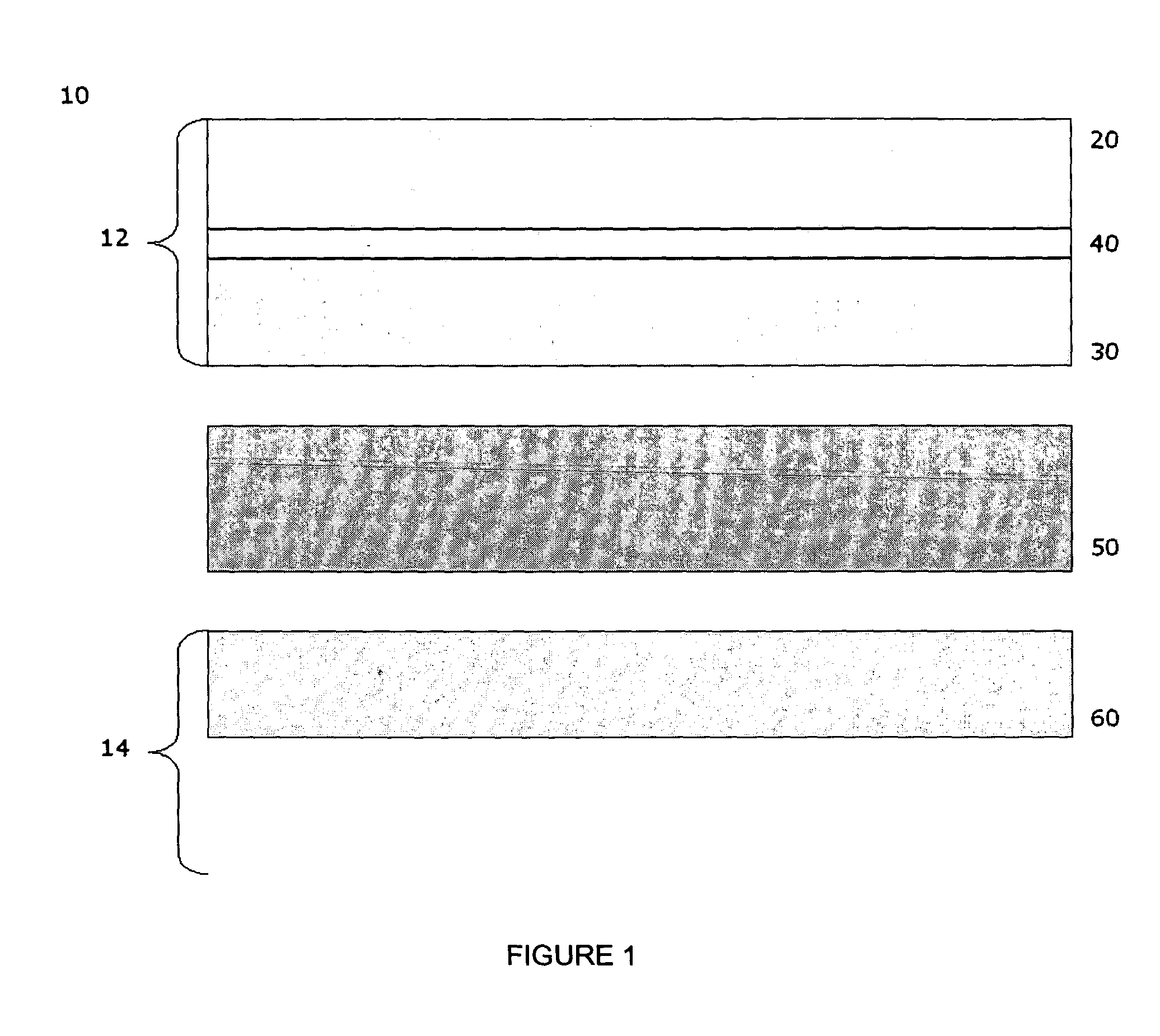
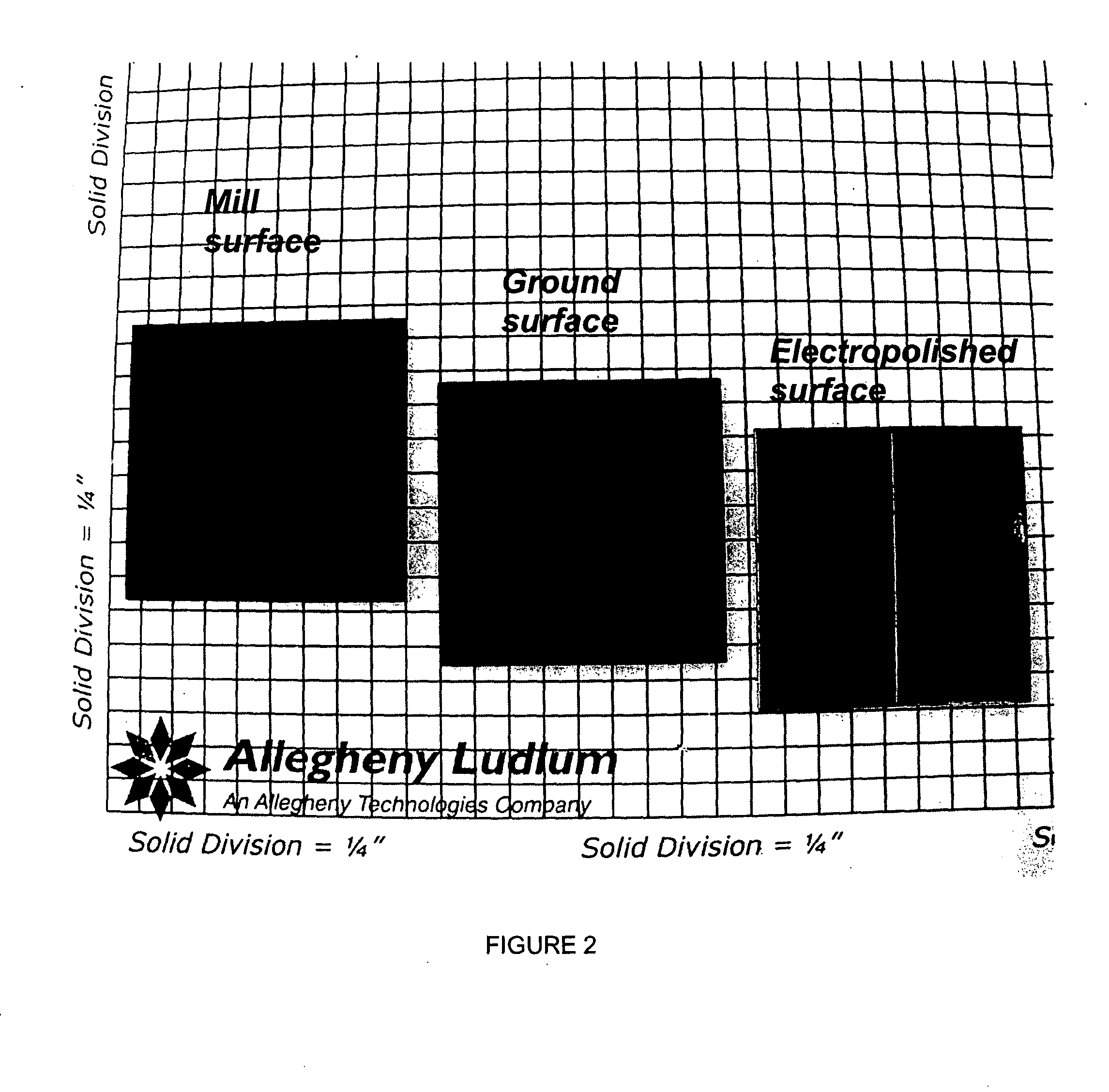
A coil of AL 453™ alloy was provided by the conventional process of casting the alloy to a slab or ingot, hot reducing to a band, cold rolling to finished gauge with intermediate stress relieving anneals, and a final anneal in hydrogen. Several 1″×2″ test coupons were prepared from the coil and processed by three different surface treatments. Each coupon had an initial thickness of 0.075″ and a standard 2BA finish, and was degreased and had finished edges. This surface finish is generally referred to herein as a “mill” surface, and samples including that surface are referred to herein as “mill” samples. Several mill samples were further processed by grinding using 120 grit SiC paper to remove nominally 0.005″ per side. Samples prepared in this way are referred to herein as “ground” samples. Several of the ground samples were electropolished in an electropolishing solution including, by volume, 25% sulfuric acid-47% phosphoric acid-28% glycolic acid for 20 minutes (samples flipped e...

example 2

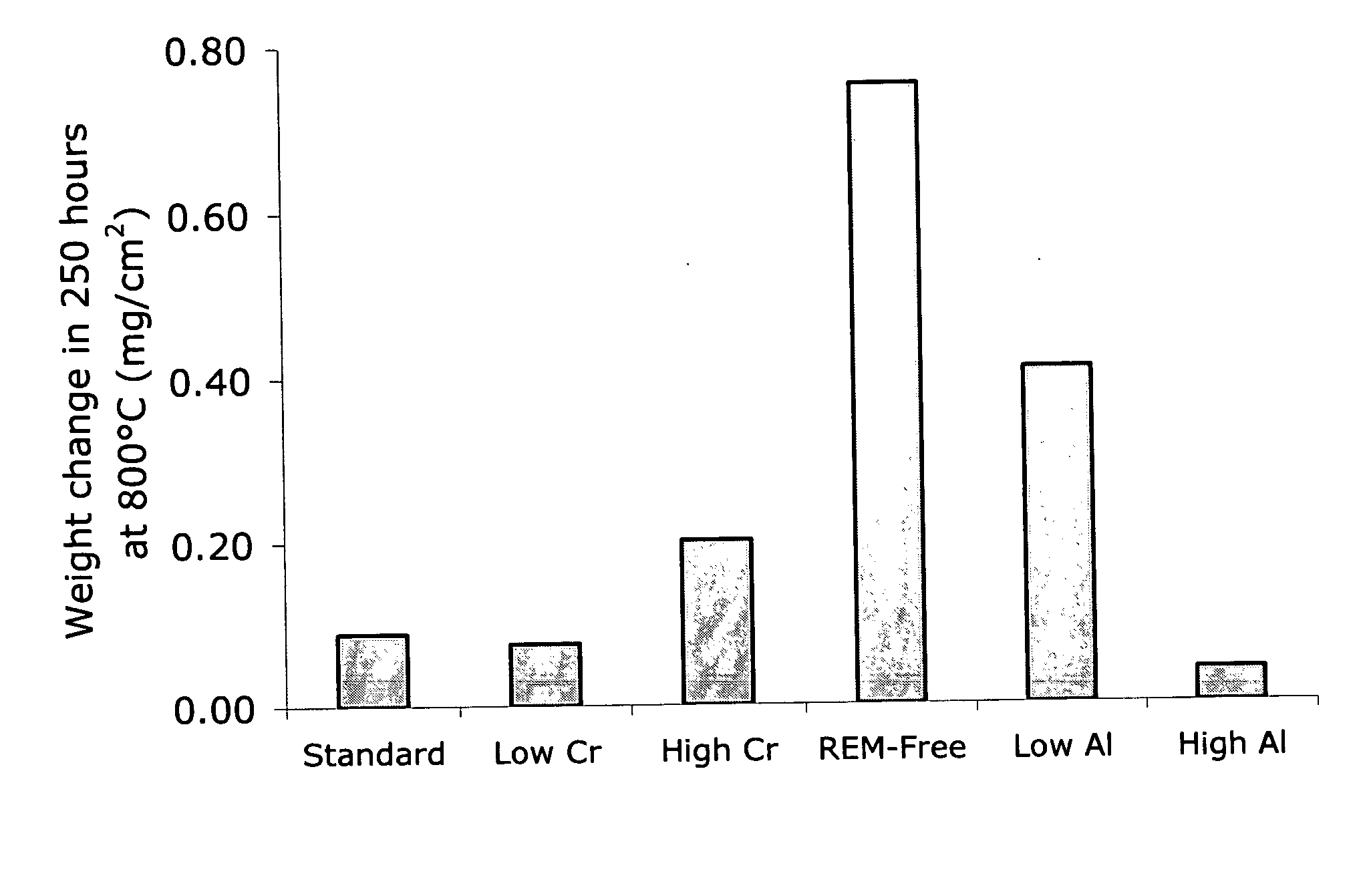
Additional testing on two coils from each of two different heats of AL 453™ alloy was conducted to assess the repeatability of electropolishing as a means to significantly enhance high temperature corrosion resistance. The starting material was processed as standard AL 453™ material, which is conventionally single-stage rolled from hot rolled band to 0.075″ and then bright annealed. Table 3 lists the quantities of prepared test samples. Table 4 describes the processes used to treat the various sample types prior to testing.

TABLE 3Pol-Re-HeatCoilMillGroundishedElectropolishedpolished89804203232C1131112103232C123111218980430323C1431112103232C13211121Total per condition44484

TABLE 4Sample DesignationSurface ProcessingMill2BA finish, as received, no further surfacepreparation.GroundAll surfaces ground with 120 grit SiC paper,removing 0.002″ (nominal) per side.PolishedAll surfaces ground with 120 grit SiC paper,removing 0.002″ (nominal) per side. All surfacesthen polished to specular f...

example 3

Glancing incidence X-ray diffraction techniques were used to characterize the nature of the oxide film formed on embodiments of the electrochemically modified ferritic stainless steels of the present disclosure. The oxidation of conventional bright annealed AL 453™ alloy occurs in a manner typical for a heat-resistant stainless steel containing more than about 16% chromium by weight. Al2O3 is thermodynamically stable and should form in direct contact with the surface of the alloy. A minimum of about 3 weight percent aluminum, however, is needed to ensure rapid enough diffusion to the metal / oxide interface to sustain the growth of a continuous layer of alumina. Therefore, in conventional bright annealed AL 453™ alloy, a chromium oxide (Cr2O3) layer forms in direct contact with the alloy surface, along with significant amounts of iron and spinel oxides. Aluminum oxide particles form in the alloy adjacent the scale / alloy interface. Such behavior is consistent with the established theo...


PUM

PropertyMeasurementUnit
Temperatureaaaaaaaaaa
Timeaaaaaaaaaa

Abstract

A method for making a ferritic stainless steel article having an oxidation resistant surface includes providing a ferritic stainless steel comprising aluminum, at least one rare earth metal and 16 to less than 30 weight percent chromium, wherein the total weight of rare earth metals is greater than 0.02 weight percent. At least one surface of the ferritic stainless steel is modified so that, when subjected to an oxidizing atmosphere at high temperature, the modified surface develops an electrically conductive, aluminum-rich, oxidation resistant oxide scale comprising chromium and iron and a having a hematite structure differing from Fe2O3, alpha Cr2O3 and alpha Al2O3. The modified surface may be provided, for example, by electrochemically modifying the surface, such as by electropolishing the surface.

Description

BACKGROUND OF THE INVENTION 1. Field of the Invention The present disclosure relates to methods of making ferritic stainless steels having at least one oxidation resistant surface. The present disclosure also relates to ferritic stainless steels including at least one oxidation resistant surface, and further relates to articles of manufacture formed of or including such ferritic stainless steels. 2. Description of the Invention Background Fuel cells are energy conversion devices that generate electricity and heat by electrochemically combining a gaseous fuel and an oxidizing gas via an ion-conducting electrolyte. A primary feature of fuel cells is the ability to convert chemical energy directly into electrical energy in the absence of combustion, which provides significantly higher conversion efficiencies than reciprocating engines, gas turbines and other conventional thermomechanical methods of producing energy. For the same power output, fuel cells produce substantially less c...

Claims


Application Information

Patent Timeline
IPC IPC(8): C23C8/10C23C8/18C25F3/24H01M8/02
CPCC22C38/005Y10T29/49108C22C38/18C23C8/18C25F3/24H01M8/0204H01M8/021H01M8/0223Y02E60/50C22C38/50C22C38/04C22C38/02C22C38/001C22C38/58C22C38/06Y02P70/50C25F3/00
Inventor RAKOWSKI, JAMES A.
Owner ATI PROPERTIES
Why Eureka
Try Eureka