Corrosion-resistant member and method forproducing same

Inactive Publication Date: 2006-01-26
TOSOH CORP
View PDF10 Cites 11 Cited by
  • Summary
  • Abstract
  • Description
  • Claims
  • Application Information

AI Technical Summary

Benefits of technology

[0012] Under the foregoing present situation, the present inventors made extensive and intensive investigations. As a result, it has been found that a member comprising a base material sprayed with a corrosion resistant glass sprayed coating containing at least one element of elements consisting of the group of the group 2a, group 3a and group 4a of the periodic table of element, particularly a corrosion resistant glass sprayed coating of an aluminosilicate glass or zirconia silicate glass containing at least one element of elements consisting of the group of the group 2a, group 3a and group 4a of the periodic table of element has not only especially high corrosion resistance to corrosive gases or corrosive gas-containing plasma but also sufficient heat resistance as a part to be used in portions to be heated. Also, it has been found that the corrosion resistant member becomes high in the corrosion resistance to corrosive gases or plasma as compared with bulk glass members having the same composition. Further, it has been found that for

Problems solved by technology

However, these members involved such problems that the member reacts with a fluorine based gas to form a fluoride, thereby causing the generation of particles within the device and that the member is exhausted within a short period of time.
However, even in such sintered bodies, corrosion in the crystal grain boundary of sintered particles was unavoidable, and the generation of particles due to dropout of the crystal particles was unavoidable.
However, these corrosion resistant glasses are not only expensive but also insufficient in the heat resistance for using them with good safety in the semiconductor process, and therefore, portions which can be used as vessels or parts to be used in the semiconductor manufacturing process were limited.
However, according to the conventional spraying technologies, since the formation of a sprayed coating of glass was difficult, metals or ceramics were principally used in the conventional formation of a protective film by spraying.
However, it is described that the conventional glasses to be used for spraying of glass are a glass having a softening point lower than 1,000° C., whereas in glasses having a softening point exceeding 1,000° C., the adhesion is poor and the porosity is increased so that a uniform sprayed coating is not obtained (see, for example, JP-A-64-13324).
Namely, so far, it was obvious that a sprayed coating of glass could not be formed with good adhesion on an oxide, and there was no technology for spraying a glass having a high softening point of 1,000° C. or higher on a base material with good adhesion,

Method used


Image

  • Corrosion-resistant member and method forproducing same
  • Corrosion-resistant member and method forproducing same
  • Corrosion-resistant member and method forproducing same

Examples


example 1

1) Preparation of Base Material:

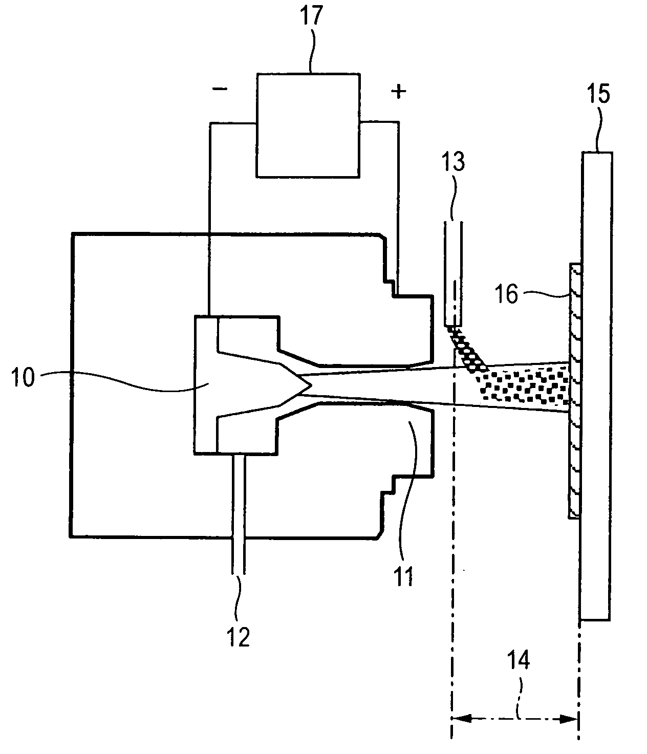
[0079] On a quartz glass base material, nitrogen was flown as a plasma gas at a rate of 5 SLM to form plasma with a power of 21 kW using a double torch type plasma spraying device as shown in FIG. 5, and a spraying gun was moved at a rate of 80 mm / min while adjusting a spraying distance at 80 mm without supplying a raw material powder, thereby pre-heating the quartz glass base material. At this time, the plasma was in the laminar state with a length of about 30 cm. Next, a quartz powder was supplied at a rate of 4.5 g / min and sprayed while moving the spraying gun at a rate of 160 mm / sec. The subject sprayed surface was exposed with plasma without supplying a raw material powder while moving the spraying gun at a rate of 300 mm / min, thereby melting a powdered substance adhered onto the surface. There was thus prepared a quartz glass base material coated with a quartz sprayed coating having a surface roughness Ra of 15 μm (base material A).

[0080] Fur...

example 2

1) Formation and Evaluation of Corrosion Resistant Sprayed Coating:

[0086] Using a spraying powder prepared from an oxide of each of metal elements shown in Table 2 in the same manner as in Example 1-2) for the base material D prepared in Example 1-1), nitrogen was flown as a plasma gas at a rate of 16 SLM to form plasma with a power of 32 kW using a double torch type plasma spraying device as shown in FIG. 5, and the plasma was sprayed 25 times at a spraying distance of 100 mm and a flow rate of the raw material powder of 7 g / min while moving a spraying gun at a rate of 400 mm / sec and at a pitch of 3 mm, to form a corrosion resistant sprayed coating. At this time, the plasma flame was in the turbulent state. For the sprayed coating, the coating quality was confirmed as the performance evaluation by observing a cross section of the sprayed coating by SEM; and dense one was designated as “0”, and porous one was designated as “x”. Also, the vitrification was confirmed by the X-ray di...


PUM

PropertyMeasurementUnit
Surface roughnessaaaaaaaaaa
Concentrationaaaaaaaaaa

Abstract

Members to be used in CVD devices, plasma treatment devices, etc. are exhausted by reaction with a corrosive gas or etching with plasma, and therefore, there were encountered problems such as staining of products due to the generation of particles and a reduction of the yield productivity. Also, glasses resistant to corrosive gases or plasma are weak in the heat resistance, and therefore, applications to be employed were limited.
Members containing a heat-resisting base material having coated thereon a corrosion resistant glass containing at least one element selected from the group consisting of elements of the group 2a, group 3a and group 4a, especially an aluminosilicate or zirconia silicate based glass sprayed coating have high corrosion resistance to corrosive gases and plasma and high heat resistance and are less in the generation of particles.

Description

TECHNICAL FIELD [0001] The present invention relates to a member to be used in CVD devices and plasma treatment devices (plasma etching devices) in manufacturing of semiconductors, etc., and so on, and in particular, to a member having high corrosion resistance to corrosive gases or plasma and also high heat-resistant strength. BACKGROUND ART [0002] Corrosive gases are frequently used for plasma etching in the manufacturing step of semiconductors, etc., and cleaning application of CVD devices. For these corrosive gases, fluorine based and chlorine based gases, and the like are used. As the fluorine based gases, CF4, C2F6, C3F8, CHF3 / CF4, SF6, and so on are used (see, for example, JP-A-2000-223430); and for the Cl based gases, Cl2, BCl3, CCl4, and so on are used (see L. Peters, Plasma Etch Chemistry: The Untold Story, Semic. Intl., 15(6), 66 (1992)). Further, it is also proposed to use HF, F2, or NF3 (see, for example, JP-A-2000-223430, JP-A-2000-248363, and JP-A-05-090180). [0003] I...

Claims


Application Information

Patent Timeline
IPC IPC(8): B32B17/06B32B15/00B32B19/00C23C4/10
CPCC03C3/062Y02T50/67C03C3/085C03C3/095C03C8/02C03C15/00C03C17/002C03C17/007C03C17/04C03C17/3417C03C19/00C03C2217/78C23C4/10C23C4/105C23D5/04C03C3/083C23C4/11Y02T50/60
Inventor ABE, MASANORITAKAHASHI, KOYATAARAI, KAZUYOSHITAKAHATA, TSUTOMUHASHIMOTO, SHINKICHIKOHGO, MASANORI
Owner TOSOH CORP
Why Eureka
Try Eureka