Process for pyrolytic heat recovery enhanced with gasification of organic material
- Summary
- Abstract
- Description
- Claims
- Application Information
AI Technical Summary
Benefits of technology
Problems solved by technology
Method used
Image

Examples
embodiment a
, the Base Case
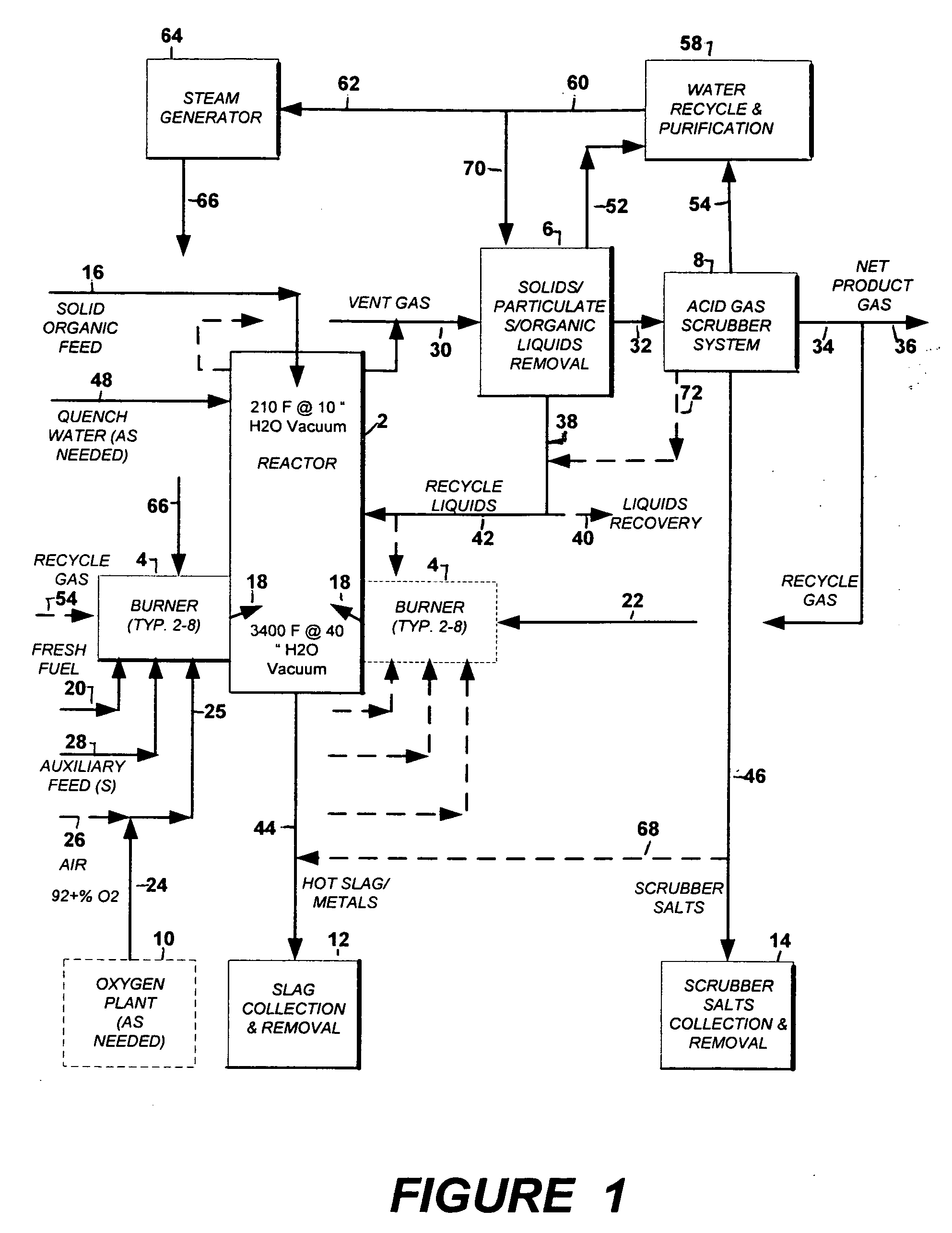
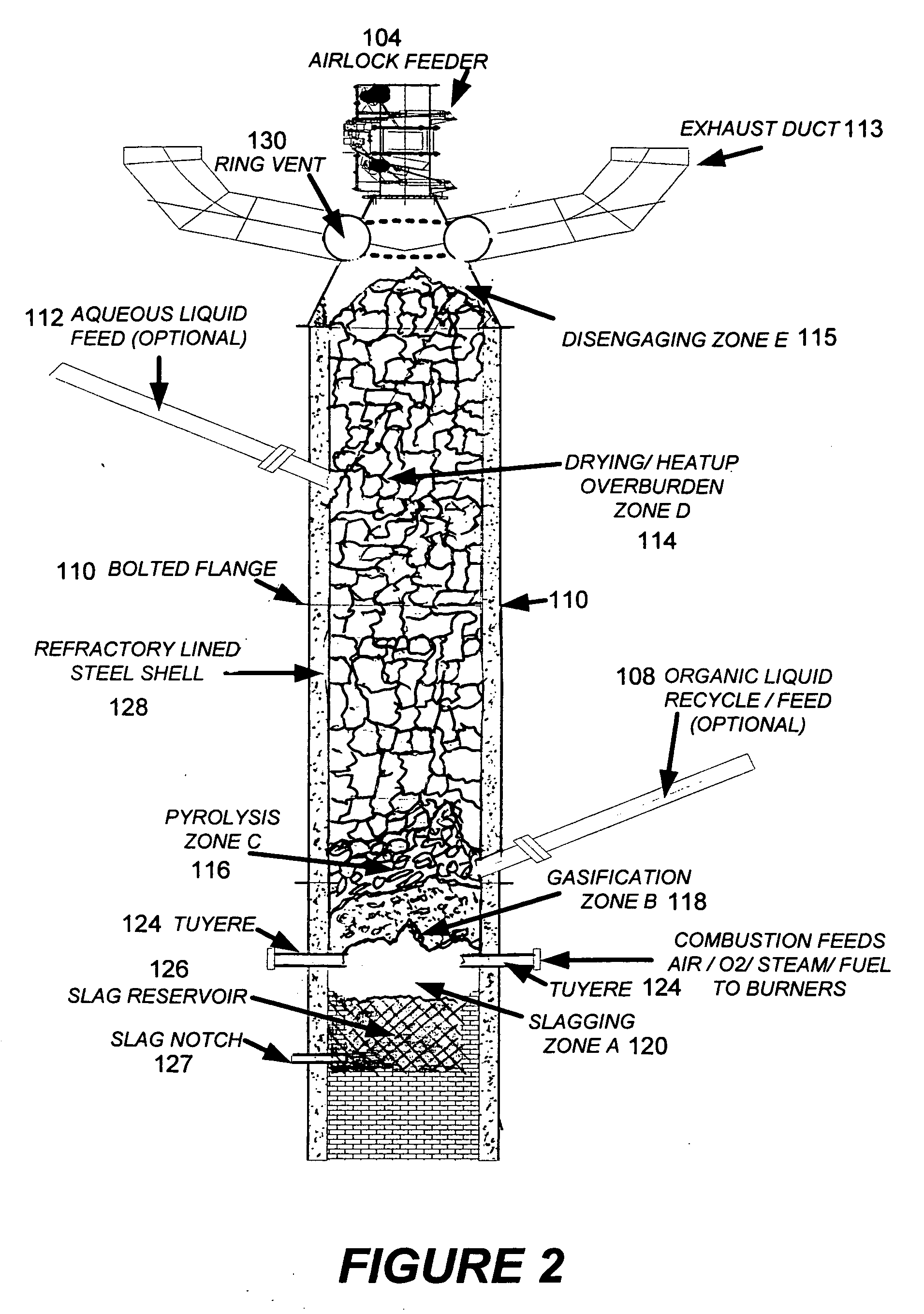
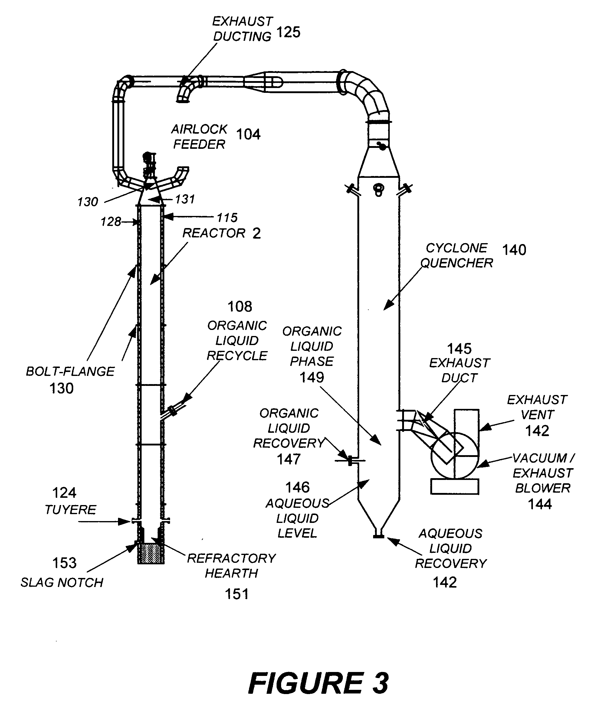
[0125] In a preferred embodiment of PHREG that we call the Base Case, waste materials are reduced to a uniform size and fed to the top of a vertical shaft reactor system, flowing downward in contact with hot gases flowing upward. As they pass downward, the wastes are heated by the counter-current hotter gases flowing up from the bottom of the reactor. The wastes pass successively through a series of stages where they are (Zone D) dried at temperatures up to 250° F., (Zone C) pyrolyzed at temperatures of 500 to 900° F., (Zone B) gasified at 1500 to 2700° F. and (Zone A) mixed with any residual glass, inorganic ash, and metals being liquefied in the range of 2000 to 3600° F. to form a slag that is removed from the bottom of the reactor.
Driver Gas
[0126] The thermochemical driver gas, entering the bottom of the reactor in the liquefaction zone (Zone A), is formed initially by combustion of commercially available natural gas or fuel oil, or a mixture thereof, and mixed ...
embodiment b
, Employing Water Based Industrial Waste Mixed into the Feed
[0142] In another preferred embodiment of PHREG, reactor feed materials are supplemented with non-form-stable, water-based or water-containing consumer and / or industrial waste or other waste organic components. This supplemental material can be sprayed or squeezed onto the base solid material at any point from the feed material hold bunkers up to the primary feed port into the reactor. The supplemental material (typically solutions, emulsions, sludges) becomes mixed into the primary feed and enters the reactor in a fashion consistent with the method of the Base Case.
[0143] The total amount of this supplemental feed is smaller than the total bulk of top-fed material. The amount is determined by the types of all feed material to the reactor, how well the supplemental feed is adsorbed by the solids, the corresponding reactor temperature profile needs, and driver gas conditions lower in the reactor.
[0144] All other operations...
embodiment c
, Employing Solid Industrial Waste or Organic Material Mixed into Feed
[0145] In another preferred embodiment of PHREG, reactor feed materials are supplemented by solid industrial waste or other solid organic components such as wood, coal, coke, oil share, tars, and petroleum residues. This supplemental material can be added to the base solid material at any point from the feed material hold bunkers up to the primary feed port into the reactor. This supplemental material will become mixed into the primary feed and enter the reactor in a fashion consistent with the method of the Base Case.
[0146] The total amount of this supplemental feed is smaller than the total bulk of top-fed material and is determined by the types of all feed material to the reactor, the ability of the solid materials to adsorb the supplemental feed, the corresponding reactor temperature profile needs, and driver gas conditions lower in the reactor. One basic determining factor is the organic content of the mater...
PUM
 Abstract
Description
Claims
Application Information
 - R&D
- Intellectual Property
- Life Sciences
- Materials
- Tech Scout
- Unparalleled Data Quality
- Higher Quality Content
- 60% Fewer Hallucinations
Browse by: Latest US Patents, China's latest patents, Technical Efficacy Thesaurus, Application Domain, Technology Topic, Popular Technical Reports.
© 2025 PatSnap. All rights reserved.Legal|Privacy policy|Modern Slavery Act Transparency Statement|Sitemap|About US| Contact US: help@patsnap.com