
Material for organic electroluminescent device and organic electroluminescent device using same

a technology of electroluminescent devices and materials, which is applied in the direction of discharge tube luminescnet screens, natural mineral layered products, etc., can solve the problems of symmetrical structure, too symmetrical to avoid the generation of crystal growth, and the tendency of the host compound to crystallize, etc., to achieve superior heat resistance, prolong the life, and enhance the efficiency of light emission

Inactive Publication Date: 2007-05-10
IDEMITSU KOSAN CO LTD
View PDF2 Cites 24 Cited by
  • Summary
  • Abstract
  • Description
  • Claims
  • Application Information

AI Technical Summary

Benefits of technology

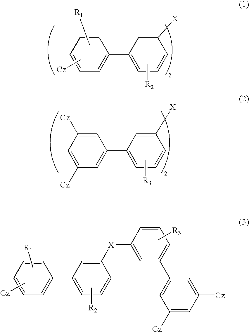
[0019] The present invention has been made to overcome the above problems and has an object of providing a material for the organic electroluminescence device with an enhanced efficiency of light emission, free from defects in pixels, superior in heat resistance and with prolonged lifetime, together with the organic electroluminescence device employing the material.
[0020] As a result of intensive and extensive researches for overcoming the above problems, the inventors have found that using a compound with great molecular weight and with poor symmetry as a host material enables to achieve an organic EL device with an enhanced efficiency of light emission, free from defects in pixels, superior in heat resistance and with prolonged lifetime. The present invention has been accomplished on the basis of the above finding.
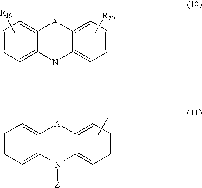
[0025] Employing the compound represented by any one of general formulae (1) to (3) of the present invention as the material for an organic electroluminescence device provides the organic electroluminescence device with an enhanced current efficiency of light emission, without any pixel defects, with superiority in heat resistance and with prolonged lifetime. Therefore, the organic EL device of the present invention is very useful for applications such as light sources of various electronic instruments. THE PREFERRED EMBODIMENT TO CARRY OUT THE INVENTION
[0118] Further in the organic EL device of the present invention, it is preferable to employ an inorganic compound such as an insulating material or a semiconductor for an electron injecting layer. The electron injecting layer employing an insulating material or a semiconductor effectively prevents leak in the electric current and improves the electron injecting capability.
[0122] It is preferable that the organic EL device of the present invention has a hole transporting layer between the light emitting layer and the anode and that the hole transporting layer comprises an arylamine derivative as a main component. Further, it is preferable that the triplet energy of the hole transporting material in the hole transporting layer falls within a range of from 2.52 to 3.7 eV, more desirably from 2.8 to 3.7 eV. An employment of the hole transporting material having the above triplet energy range enables to prevent quenching an excitation energy of the light emitting layer.

Problems solved by technology

However, there were problems that the host compound tends to crystallize because its glass transition temperature is 110° C. or less and further, because it is too symmetrical and that short circuit or pixel defect generates in the heat resistance test of the organic EL device.
Furthermore, it was found that a crystal growth generates at the position where there is a foreign matter or a protrusion of an electrode in an occasion of vapor deposition, and that the defects generate more than the primary stage before the heat resistance test.
However, it is too symmetrical to evade the crystal growth generation at the position where there is a foreign matter or a protrusion of an electrode in an occasion of vapor deposition, or the defects generation more than the primary stage before the heat resistance test.
Despite an improvement of heat resistance in Patent Literature 6, compounds disclosed in it still have favorably symmetric because they have phenylene structures composing the compounds with bonding styles coupling at almost all para positions, remaining only central benzene ring bonding at meta position, and accordingly, a problem of crystallization was unavoidable.
Accordingly, it was difficult to convey energy from the host to the phosphorus photoluminescent dopant, and there were problems of causing degradation in efficiency of light emission particularly about blue phosphorus photoluminescent devices.
Therefore, there was a problem that the compound reduces the triplet excitation energy.

Method used


Image

  • Material for organic electroluminescent device and organic electroluminescent device using same
  • Material for organic electroluminescent device and organic electroluminescent device using same
  • Material for organic electroluminescent device and organic electroluminescent device using same

Examples


synthesis example 1 (

Synthesis of Compound (C5))

[0129] The route for synthesis of Compound (C5) is shown in the following.

(1) Synthesis of Intermediate Compound (IM1)

[0130] Placing 3,3′-dibromobiphenyl in an amount of 50 g (160 mmol), carbazole in an amount of 18.4 g (110 mmol), copper iodide 3.0 g (16 mmol), potassium phosphate in an amount of 46.6 g (220 mmol), trans 1,2-cyclohexanediamine in an amount of 18.2 g (160 mmol) and 1,4-dioxane in an amount of 500 milliliter into a three neck flask having a capacity of 1 liter, the resultant solution was stirred under an atmosphere of argon gas at a temperature of 105° C. for 12 hours. Afterwards, cooling the reacted solution down to a room temperature and adding 160 milliliter of water, extractions were conducted with the use dichloro-methane for 3 times. After drying an organic layer with the use of unhydride magnesium sulfate, the solvent was concentrated under reduced pressure.

[0131] Treating residues in a silicagel column, dicarbazolyl substance, ...

synthesis example 2 (

Synthesis of Compound (C8))

[0137] The route for synthesis of Compound (C8) is shown in the following.

[0138] Under the atmosphere of Argon gas, 3,5-dibromobiphenyl in an amount of 6.2 g (20 mmol), para-(carbazoly-9-yl) phenylboronic acid in an amount of 5.8 g (20 mmol), tetrakistriphenylphosphinepalladium 0 valence (Pd(PPh3)4) in an amount of 460 mg (0.4 mmol), dimethoxyethane in an amount of 100 milliliter and 10% by weight aqueous solution of sodium carbonate in an amount of 64 g (60 mmol) were placed into a three neck flask with a capacity of 200 milliliter, and the resultant solution was stirred at a temperature of 78° C. for 10 hours.

[0139] After completion of the reaction, the solution was cooled down to a room temperature and precipitated solids were separated by filtration. Adding toluene in an amount of 100 milliliter into the filtrate, an organic layer was washed by means of a separatory funnel with a use of water and a saturated solution of sodium chloride successively....

synthesis example 3 (

Synthesis of Compound (C14))

[0145] The route for synthesis of Compound (C14) is shown in the following.

(1) Synthesis of Intermediate Compound (IM5)

[0146] Under the atmosphere of argon gas, 1-bromo-3-iodebenzene in an amount of 5.0 g (18 mmol), para-(carbazolyl-9-yl) phenylboronic acid in an amount of 5.2 g (18 mmol), tetrakistriphenylphosphinepalladium 0 valence (Pd(PPh3)4) in an amount of 414 mg (0.36 mmol), dimethoxyethane in an amount of 100 milliliter and 10% by weight aqueous solution of sodium carbonate in an amount of 58 g (54 mmol) were placed into a three neck flask with a capacity of 300 milliliter, and the resultant solution was stirred at a temperature of 80° C. for 12 hours. After completion of the reaction, the solution was cooled down to a room temperature and adding toluene in an amount of 100 milliliter into the filtrate, an organic layer was washed by means of a separatory funnel with a use of water and a saturated solution of sodium chloride successively. The ...


PUM

PropertyMeasurementUnit
glass transition temperatureaaaaaaaaaa
work functionaaaaaaaaaa
thicknessaaaaaaaaaa

Abstract

A material for organic electroluminescence device with specific structure having poor symmetry. An an organic electroluminescence device comprising a cathode, an anode and an organic thin film layer which is sandwiched between the cathode and the anode and comprises at least one layer, wherein at least one layer in the organic thin film layer contains a material for the organic electroluminescence device described above. An organic electroluminescence device with excellent efficiency of light emission, without pixel defects and which is superior in heat resistance is obtained.

Description

TECHNICAL FIELD [0001] The present invention relates to a material for an organic electroluminescence device and an organic electroluminescence device employing the same. Particularly, the present invention relates to the material for the organic electroluminescence device with an enhanced efficiency of light emission, free from defects in pixels, superior in heat resistance and with prolonged lifetime, together with the organic electroluminescence device employing the material. BACKGROUND ART [0002] An organic electroluminescence (“electroluminescence” will be occasionally referred to as “EL”, hereinafter) device is a spontaneous light emitting device which utilizes the principle that a fluorescent substance emits light by energy of recombination of holes injected from an anode and electrons injected from a cathode when an electric field is applied. Since an organic EL device of the laminate type driven under a low electric voltage was reported by C. W. Tang et al. of Eastman Kodak...

Claims


Application Information

Patent Timeline
Patent Type & Authority Applications(United States)
IPC IPC(8): H01L51/54C09K11/06H05B33/14H05B33/22H10K99/00
CPCC09K11/06Y10S428/917C09K2211/1029C09K2211/1033C09K2211/1037C09K2211/104C09K2211/1044C09K2211/1059C09K2211/185C09K2211/186H01L51/0059H01L51/0072H01L51/0081H01L51/5016H01L51/5092H05B33/14C09K2211/1007H10K85/631H10K85/6572H10K85/324H10K50/171H10K50/11H10K2101/10
Inventor IWAKUMA, TOSHIHIROTOMITA, SEIJIITO, MITSUNORI
Owner IDEMITSU KOSAN CO LTD
Learn More