
Deposition System, Method And Materials For Composite Coatings

a technology of composite coatings and coatings, applied in the field of composite coatings deposition systems, methods and materials, can solve the problems of nitrides, carbonitrides, borides, etc., and achieve the effect of excellent structural properties and high corrosion resistan

Inactive Publication Date: 2007-10-18
BELASHCHENKO VLADIMIR E
View PDF29 Cites 61 Cited by
  • Summary
  • Abstract
  • Description
  • Claims
  • Application Information

AI Technical Summary

Benefits of technology

[0012] The present invention is directed to composite metal-ceramic powders used for depositing composite coatings on a selected surface. Several embodiments of the present invention are directed to methods and systems for producing such composite powders. Several embodiments of the present invention are also directed to methods and systems for depositing the metal-ceramic composite powders to form coatings. Advantageously, the deposited coatings exhibit high corrosion resistance and excellent structural properties.
[0024] According to a preferred embodiment, the novel composite metal-ceramic powders have an amorphous metallic binder to provide coatings with a combination of low cost, high hardness, high corrosion and oxidation resistance as well as high deposition efficiency. Preferably, the coatings are deposited using the thermal spray process. Additional embodiments of the present invention include thermal spray processes and thermal spray equipment optimized for specific composite metal-ceramic powders for producing the coatings.
[0025] Preferably, the novel composite metal-ceramic powders are used for surface modification of various substrates that require high impact resistance, excellent wear resistance, and excellent corrosion and erosion resistance even under high temperature. Preferably, the coatings are deposited using a deposition apparatus which generally provides a stream of gas having a desired temperature and velocity profile. The deposition apparatus includes a feeding module for the introduction of the powder or particulate material into the gas stream and deposition onto the desired surface. Preferably, the deposition apparatus is a high velocity thermal spray (HVTS) apparatus for spraying composite metal-ceramic powders. Alternatively, the deposition apparatus is selected from the high velocity oxygen fuel (HVOF) apparatuses like JP 5000 manufactured by Praxair-Tafa, Diamond Jet manufactured by Sulzer Metco, Jet Kote manufactured by Stellite Coatings, Inc., or the deposition apparatuses described in U.S. Pat. No. 5,932,293. Other deposition apparatuses and methods may be used as well. The technology provides very good cohesion / adhesion between ceramic components and amorphous and / or nanocrystalline metallic components during the deposition process and coating formation.

Problems solved by technology

However, in many cases, the metal (or substrate) constituting such metal parts cannot adequately satisfy the required properties by itself, and it is therefore often subjected to surface modification, particularly by forming a coating or deposition on the substrate surface.
Such compositions, comprising nitrides, carbonitrides, borides (for example, titanium carbonitride) and multicomponent metallic alloys (for example, CoCrAIY, FeCrAIY, and so on) have not yet found wide application.
Melting of the nonmetallic component of a composite powder may cause its undesirable decomposition and phase transformation as well.
Splashing often results in voids and excessive surface area of the splashed particles.
These characteristics may, consequently, result in excessive oxidation, low wear, corrosion and erosion resistance of the coated object.
However, this third coating scheme may have a very low efficiency when spraying the metal-ceramic composite powders.
Disadvantages of prior art composite materials are partially related to the metallic compounds or binders, which are based on metals like Ni and Co, and the conventional crystalline alloys with other metals like Cr, etc.
In some cases these types of binders do not provide desirable corrosion resistance, bonding with nonmetallic components of a composite material, wear and erosion resistance, toughness and some other properties determining performance of the composite material.
Notably, Co and Ni based alloys are expensive.

Method used


Image

  • Deposition System, Method And Materials For Composite Coatings
  • Deposition System, Method And Materials For Composite Coatings
  • Deposition System, Method And Materials For Composite Coatings

Examples


example 2

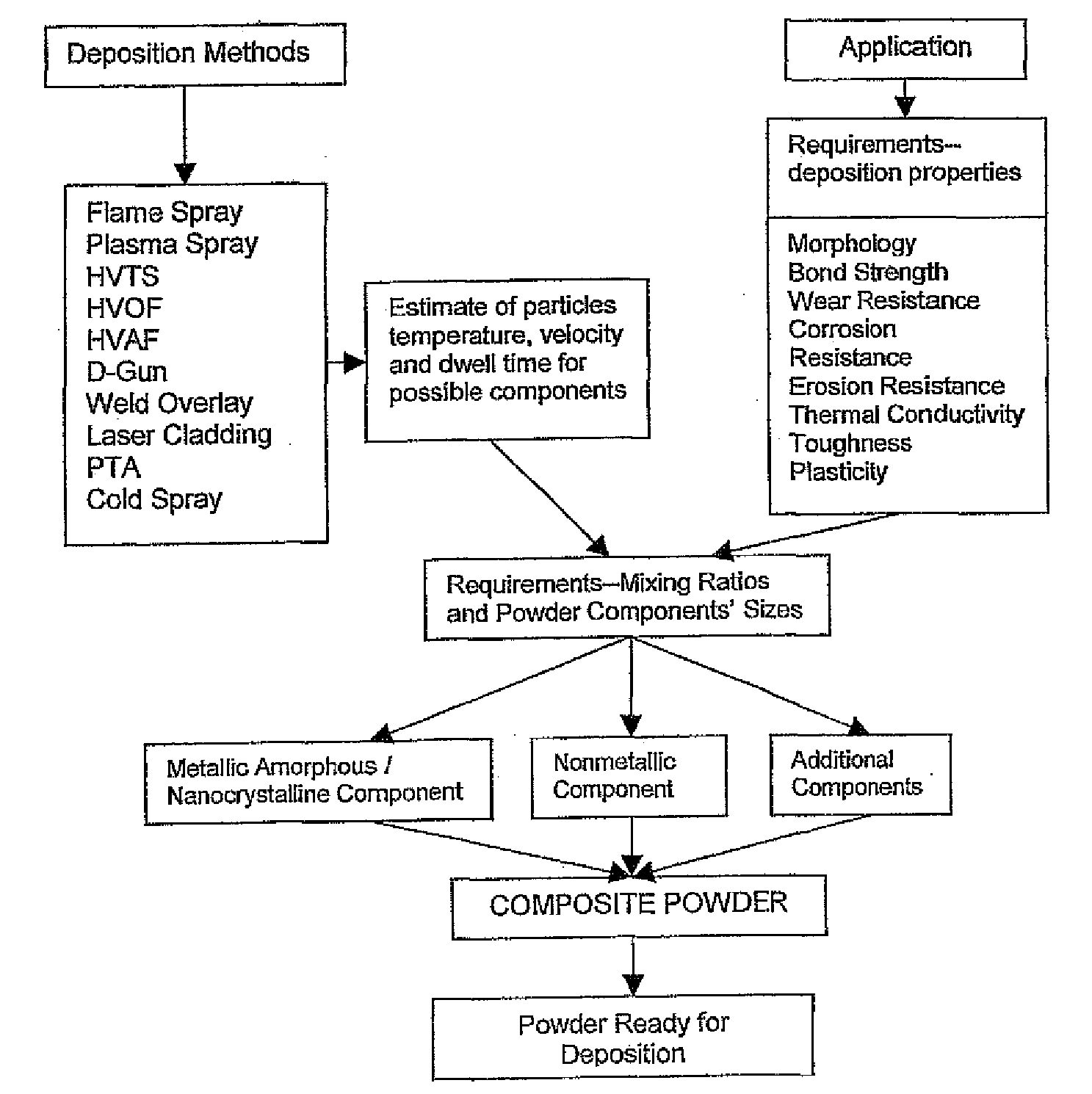
[0154] To make the composite powder designated CP-2, commercially available powders 1350VM from Praxair Surface Technologies and SHS 7170 powder manufactured by Nanosteel, Inc. are used.

[0155] Composite powder CP-2 is made as follows: the thermal spray powder having a nominal composition of 86% by weight tungsten carbide (WC), 10% by weight Cobalt (Co) and 4% by weight Chromium (Cr), or 1350VM powder, is screened through a 325 mesh sieve to insure the absence of coarse particles larger than 45-50 μm. Similarly, the amorphous metallic alloy powder, grade SHS 7170, manufactured by Nanosteel, Inc. is also screened through a 325 mesh sieve for the same purpose. SHS 7170 is composed of 25% or less Chromium, 8% or less Molybdenum, 10% or less Tungsten, 2% or less Carbon, 5% or less Manganese, 2% or less Silicon, 5% or less Boron, and a balance of Iron. Additionally, these powders are screened through a 635 mesh sieve to remove fine particles having a size of less than 15 μm. After screen...

example 3-7

[0156] Composite powders having various amounts of each component, designated as Composites No. 3 through No. 7 are prepared as described in the protocol for composite powder CP-2, above. However, powder SHS 7170 may be replaced with component SHS 7574 (also manufactured by Nanosteel, Inc.), and different quantities of each component are used for each of the different composite powders. Metallic alloy powder SHS 7574 has a composition similar to SHS 7170, but includes a higher content of Molybdenum.

ComponentsQuantity loaded inV-blenderComposite1350VmSHS 7170SHS 7574Powder(lbs.)(lbs.)(lbs.)CP-28.5015.00.00CP-38.500.001.50CP-46.500.003.50CP-56.503.500.00CP-65.005.000.00CP-75.000.005.00

example 8

[0157] To make the composite powder designated CP-8, commercially available powders 1350VM from Praxair Surface Technologies and SHS 7574 powder manufactured by Nanosteel, Inc. are used.

[0158] CP-8 is made as follows: Powder 1350VM is screened through a 325 mesh sieve to insure the absence of coarse particles larger than 45-50 μm. Metallic alloy powder SHS 7574 is then screened through a 500 mesh sieve and the resulting powder which passed the 500 mesh sieve is additionally screened through a 635 mesh sieve to obtain particles having a size of about 30 to 20 μm. After screening, 8.50 lbs of 1350VM powder and 1.50 lbs of SHS 7574 powder are loaded in a V-type blender having a capacity of about 1 cubic foot, and are blended for 30 min at 30 rpm.


PUM

PropertyMeasurementUnit
Lengthaaaaaaaaaa
Lengthaaaaaaaaaa
Lengthaaaaaaaaaa

Abstract

A composite powder for a deposition of a composite coating comprises a nonmetallic component and a metallic component, the metallic component having an amorphous structure or a nanocrystalline structure. The metallic component may include an amorphous metallic alloy. The metallic alloy may include constituents having the amorphous structure. The metallic component may include a combination of the metallic alloy existing in the amorphous state and constituents of the amorphous metallic alloy in the amorphous state. The composite metal-ceramic powders are used for depositing composite coatings on a selected surface. Disclosed are several methods and systems for producing such composite powders. Disclosed are also several methods and systems for depositing composite coatings. Advantageously, the deposited coatings exhibit high corrosion resistance, high wear resistance, and excellent structural properties.

Description

[0001] This application claims priority to U.S. Provisional Application 60 / 610,472 filed on Sep. 16, 2004, entitled “Deposition System, Method and Materials for Composite Coatings,” which is incorporated by reference. [0002] The present invention is directed to composite powders for deposition of high quality composite coatings, and systems and methods for producing such powder.BACKGROUND [0003] Metal parts of various industrial machines or general-purpose machines are required to have various properties such as impact resistance, corrosion resistance and wear resistance depending upon their respective purposes. However, in many cases, the metal (or substrate) constituting such metal parts cannot adequately satisfy the required properties by itself, and it is therefore often subjected to surface modification, particularly by forming a coating or deposition on the substrate surface. [0004] Varieties of powder compositions for different deposition processes are known and described in ...

Claims


Application Information

Patent Timeline
IPC IPC(8): C23C4/06B05B7/16H05H1/42B32B15/00B22F1/08B22F1/148C09D7/61
CPCB22F1/0096Y10T428/2982B22F9/002C22C1/1084C22C29/02C22C29/04C22C29/08C22C29/12C22C29/14C22C29/16C23C4/04C23C4/06C23C4/065C23C4/127C23C24/04H05H1/42C09D7/1216Y10T428/12181B22F3/115C23C4/067C23C4/134C09D7/61B22F1/148B22F1/08
Inventor BELASHCHENKO, VLADIMIR E.
Owner BELASHCHENKO VLADIMIR E
Learn More