[0015] Electro-osmotic flow may be generated using a wide variety of fluids and
dielectric materials. Indeed, it is an
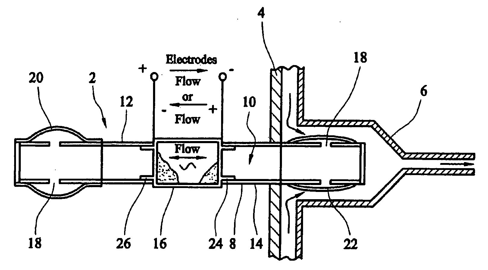
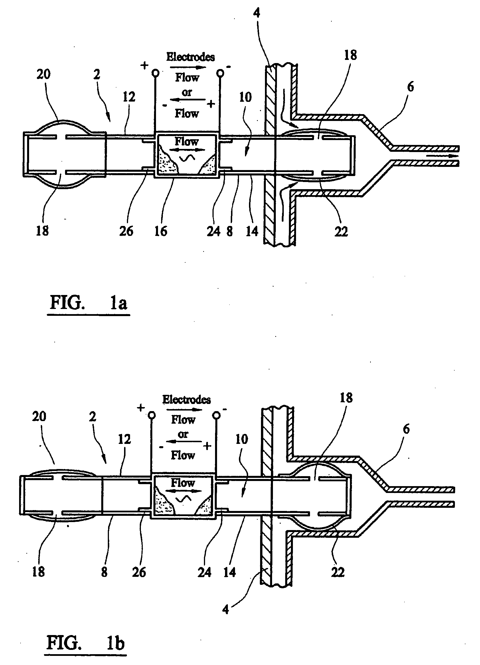
advantage of the present invention that the valve fluid can be isolated from the primary fluid so that an optimum fluid can be selected for operating the valve without reference to the particular requirements or nature of the primary fluid. The valve fluid should provide conditions that yield a high
zeta potential with respect to the porous
dielectric material. The fluid might be a pure fluid or a mixture of pure fluids. The fluid might have added to it a conducting species, especially a material which dissolves in the fluid to form ions. Preferably, the or each pure fluid should have a high dielectric constant (for example, between about 5 and 100 relative units), low dynamic
viscosity (for example, between about 0.1 and 2 centipoise) and low
conductivity (for example, between about 10.sup.-4 and 10.sup.-14 mho.multidot.m.sup.-1).
[0016] The valve fluid can include at least one additive to control the pH of the fluid. The valve fluid can include at least one additive to control the
ionic strength of the fluid. Additives should preferably dissolve completely in the fluid. The kind and concentration of additives should preferably be such as to enhance or to optimise the
zeta potential under the conditions imposed by the size of the pores in the porous dielectric medium.
[0017] The
degree of ionization of the surface sites depends on the pH of the fluid. In most cases there is a pH at which the surface is net neutral and hence the
zeta potential is zero. The zeta potential reaches a maximum value for pH values significantly above (for acidic surface sites) or pH values significantly below (for basic surface sites) the pH value at which the surface is net neutral. Ionisable surface sites can be added to a material by
chemical reaction or
grafting, or induced by creation of reactive surface
chemistry or creation of defects via
plasma or
radiation treatment.
[0018] Examples of fluids which can be used in the valve fluid include water, cyclic carbonates,
methanol,
ethanol, 1-
propanol, 2-
propanol, 1-
butanol, 1-pentanol, 1-
hexanol, 1-
heptanol,
benzyl alcohol,
nitromethane,
nitrobenzene,
butanone,
dimethoxymethane,
dimethylacetamide, dioxane, p-dioxane,
acetonitrile,
formamide,
tetrahydrofuran,
dimethyl formamide,
acetone,
acetic acid,
triethylamine,
dichloromethane,
ethylene glycol, dimethylsulphoxide,
ammonium acetate.
[0019] The valve fluid can include additives which can affect the zeta potential. Ionic species can have the opposite charge sign to the zeta potential. Ionic species can have the same charge sign as the zeta potential. Preferably, ionic species which are included in the valve fluid are monovalent. Species which ionise fully can be used to adjust the
ionic strength of the fluid. Species which ionise partially can be used to adjust the pH of the fluid. Examples of useful ionic and buffering additives include alkali-
halide salts, mineral acids and bases, organic acids and bases, phosphates, borates, acetates, citrates, malates, formates, carbonates, chlorates, nitrates, sulphates and sulphites, nitrates and nitrites,
ammonium-, methylammonium-, ethylammonium-, propylammonium-salts, BIS, MES,
TRIS, TES,
HEPES, and TEA.
[0020] Preferably, the materials of the valve fluid and the porous dielectric material are such that the zeta potential is at least about 1 mV, especially at least about 30 mV. Generally, the zeta potential will be not more than about 150 mV, for example not more than about 120 mV. The zeta potential may be either positive or negative in sign. Factors affecting the sign and magnitude of the zeta potential include the dielectric constant of the fluid, the pH of the fluid, the
ionic strength of the fluid, and the type of ions in the fluid.

